Poulan 96194000901 User Manual
Poulan 96194000901 Manual
 |
View all Poulan 96194000901 manuals
Add to My Manuals
Save this manual to your list of manuals |
Poulan 96194000901 manual content summary:
- Poulan 96194000901 | User Manual - Page 1
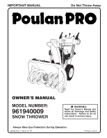
IMPORTANT MANUAL Do Not Throw Away OWNER'S MANUAL MODEL NUMBER: 961940009 SNOW THROWER WARNING: Read the Owner's Manual and follow all Warnings and Safety Instructions. Failure to do so can result in serious injury. Always Wear Eye Protection During Operation 435560 Rev 2 08.04.10 TH Printed in - Poulan 96194000901 | User Manual - Page 2
startup. CAUTION: Muffler and other engine parts become extremely hot during operation and remain understand and follow all instructions on the machine and in the manual(s) before operating this powered equipment Vibration is generally a warning of trouble. from the truck or trailer and refuel - Poulan 96194000901 | User Manual - Page 3
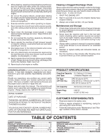
moving parts instructions under "Maintenance" and "Storage" sections of this owner's manual. TABLE OF CONTENTS SAFETY RULES 2-3 MAINTENANCE 14-15 PRODUCT SPECIFICATIONS 3 SERVICE AND ADJUSTMENTS 16-18 CUSTOMER RESPONSIBILITIES 3 STORAGE 19 ASSEMBLY / PRE-OPERATION 5-7 TROUBLESHOOTING - Poulan 96194000901 | User Manual - Page 4
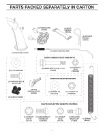
PARTS PACKED SEPARATELY IN CARTON (1) POWER CORD (198563) (1) MULTIWRENCH (180684) (3) RETAINER SPRINGS (169675) (2) FLAT WASHERS (2) SHEAR BOLTS 1/4-20 x 1-3/4 (192090) (2) LOCKNUTS 1/4-20 (73800400) (2) CARRIAGE BOLTS 3/8-16 x 2.25 (2) - Poulan 96194000901 | User Manual - Page 5
these instructions and this manual in its entirety before you attempt to assemble or operate your new snow thrower. Reading the entire manual will familiarize cover. Store the extra shear bolts, nuts and multi-wrench provided in parts bag in the toolbox. NOTE: The multi-wrench may be used for - Poulan 96194000901 | User Manual - Page 6
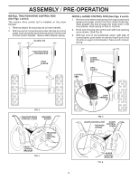
control bracket. Secure with retainer spring. PLASTIC TIE INSTALL AUGER CONTROL ROD (See Figs. 5 and 6) 1. Retrieve vinyl sleeve and spring from bag of parts and retrieve the auger control rod from carton chute tray. Slide straight rod end through the small hole in the vinyl sleeve. Hook spring in - Poulan 96194000901 | User Manual - Page 7
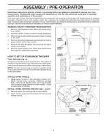
ASSEMBLY / PRE-OPERATION INSTALL DISCHARGE CHUTE / CHUTE ROTATER HEAD (See Fig. 7) NOTE: The multi-wrench provided in your parts bag may be used to install the chute rotater head. 1. Place discharge chute assembly on top of chute base with discharge opening toward front of - Poulan 96194000901 | User Manual - Page 8
yourself with the location of various controls and adjustments. Save this manual for future reference. These symbols may appear on your snow READ AND FOLLOW ALL SAFETY INFORMATION AND INSTRUCTIONS BEFORE USE OF THIS PRODUCT. KEEP THESE INSTRUCTIONS FOR FUTURE REFERENCE. IGNITION KEY. INSERT - Poulan 96194000901 | User Manual - Page 9
MUFFLER GASOLINE FILLER CAP CHOKE CONTROL OPERATION ELECTRIC START BUTTON POWER CORD PLUG AUGER CONTROL DISCHARGE CHUTE CONTROL LEVER LEVER DRIVE SPEED CONTROL LEVER DEFLECTOR REMOTE CONTROL TRACTION DRIVE CONTROL LEVER LEVER CHUTE DEFLECTOR SAFETY IGNITION KEY ON / OFF SWITCH PRIMER FUEL - Poulan 96194000901 | User Manual - Page 10
CONTROL SNOW DISCHARGE (See Fig. 13) WARNING: Snow throwers have exposed rotating parts, which can cause severe injury from contact, or from material thrown from chute or auger become clogged, shut-off engine and wait for all moving parts to stop. Use the clean-out tool, NOT YOUR HANDS, to unclog - Poulan 96194000901 | User Manual - Page 11
tool to dislodge this blockage. When cleaning, repairing, or inspecting, make certain all controls are disengaged and the auger/impeller and all moving parts have stopped. Disconnect the spark plug wire and keep the wire away from the spark plug to prevent accidental starting. • Release the auger - Poulan 96194000901 | User Manual - Page 12
wait for all moving parts to stop. 2. Adjust reversed, providing additional service before requiring replacement. Replace in the Maintenance section of this manual. ADD GASOLINE (See Fig. 19) To avoid engine problems, the fuel system season. See Storage Instructions for additional information. - Poulan 96194000901 | User Manual - Page 13
downwind whenever possible. • Adjust the skid plates to proper height for current snow conditions. See "TO ADJUST SKID PLATES" in this section of this manual. • For extremely heavy snow, reduce the width of snow removal by overlapping previous path and moving slowly. • Keep engine clean and clear of - Poulan 96194000901 | User Manual - Page 14
instructed in this manual. Some adjustments will need to be made periodically to properly maintain your snow thrower. All adjustments in the Service and Adjustments section of this manual schedule in this manual. NOTE: Use only Original Equipment Manufacturer (OEM) parts to service this unit. Failure - Poulan 96194000901 | User Manual - Page 15
due to slow leaks, tire sealant may be purchased from your local parts dealer. Tire sealant also prevents tire dry rot and corrosion. Check the hole in wheel axle (See "TO REMOVE WHEELS" in the Service and Adjustments section of this manual). 7. Remove oil fill cap/dipstick. Be careful not to allow - Poulan 96194000901 | User Manual - Page 16
service or adjustments: 1. Be sure the on/off switch is in the OFF position. 2. Remove safety ignition key. 3. Make sure the augers and all moving parts discharged, see "TO CONTROL SNOW DISCHARGE" in the Operation section of this manual. SHEAR BOLTS (See Fig. 20) AUGER SHEAR BOLTS Both right and left - Poulan 96194000901 | User Manual - Page 17
should be replaced. It is recommended that the belt(s) be replaced by a service center/department. NOTE: It is recommended that both the auger and traction drive COVER - See "TO REMOVE BELT COVER" in this section of this manual. 4. REMOVE ENGINE PULLEY - Remove bolt, flat washer securing pulley to - Poulan 96194000901 | User Manual - Page 18
punctures or prevent flat tires due to slow leaks, tire sealant may be purchased from your local parts dealer. Tire sealant also prevents tire dry rot and corrosion. ENGINE See engine manual. CARBURETOR Your carburetor is not adjustable. Engine performance should not be affected at altitudes up to - Poulan 96194000901 | User Manual - Page 19
Service and Adjustments section of this manual). 3. Lubricate as shown in the Maintenance section of this manual. 4. Be sure that all nuts, bolts, screws, and pins are securely fastened. Inspect moving parts and/or dirt in your gasoline will cause problems. • If possible, store your snow thrower - Poulan 96194000901 | User Manual - Page 20
TROUBLESHOOTING See appropriate section in manual unless directed to an authorized service center/department. PROBLEM CAUSE CORRECTION ON position). 5. Move to FULL position. 6. Prime as instructed in the Operation section of this manual. 7. Wait a few minutes before restarting, DO NOT prime. - Poulan 96194000901 | User Manual - Page 21
. 404930X428 404933X431 72270505 155377 DESCRIPTION AUGER HOUSING SCRAPPER BAR CARRIAGE BOLT 5/16−18 X .625 NUT 5/16−18 2 1 KEY NO. 1 2 PART NO. 420497X421 420498X421 DESCRIPTION AUGER ASSEMBLY 30 LH AUGER ASSEMBLY 30 RH 01.07.019-A NOTE: All component dimensions given in U.S. inches. 1 inch - Poulan 96194000901 | User Manual - Page 22
REPAIR PARTS SNOW THROWER - MODEL 961940009 (96194000901) AUGER HOUSING / IMPELLER ASSEMBLY 5 15 14 4 11 6 11 16 12 13 11 3 12 10 11 7 8 17 1 9 37 2 9 9 33 37 32 34 30 31 31 29 28 26 27 36 20 21 22 23 25 35 24 23 22 21 18 19 2 (EXPLODED) 01.07.026-D 22 - Poulan 96194000901 | User Manual - Page 23
25 26 27 28 29 30 31 32 33 34 35 36 37 PART NO. 175321X431 427148 188909 427146 175322 178675X431 192199 405400 73800400 74780426 427942 25.4 mm IMPORTANT: Use only Original Equipment Manufacturer (O.E.M.) replacement parts. Failure to do so could be hazardous, damage your snow thrower and void - Poulan 96194000901 | User Manual - Page 24
LH 2 178777X431 SKID PLATE RH 3 72270506 CARRIAGE BOLT 5/16−18 X .75 1 4 751153 NUT 5/16−18 2 3 1 1 2 3 01.07.024-B KEY NO. 1 2 3 PART NO. 420478 411939 179582 DESCRIPTION AUGER BEARING BEARING PLUG SCREW 5/16−18 X 1.00 NOTE: All component dimensions given in U.S. inches. 1 inch - Poulan 96194000901 | User Manual - Page 25
NUT 1/4-20 *12 72250505 CARRIAGE BOLT 3/8-16 X .625 *13 751153 NUT 5/16-18 *14 184505 DEFLECTOR SPRING 15 420679 (SERVICE PART) DEFLECTOR CONTROL 16 420672 (SERVICE PART) DEFLECTOR CABLE BLACK 6 *10 *13 *12 9 8 01.09.015-B NOTE: 1. ALL ITEMS INDICATED WITH AN * ARE PROVIDED IN THE - Poulan 96194000901 | User Manual - Page 26
ASSEMBLY ADJUSTABLE CABLE ASSEMBLY HEAT SHIELD *4 01.09.010-B *5 NOTES: 1. ITEMS INDICATED WITH AN * ARE LISTED AS REFERENCE FOR SERVICE PARTS ONLY. 2 1 KEY PART NO. NO. DESCRIPTION 1 421249 STEER CABLE 2 74041024 SCREW 10−24 X 1.50 01.15.009-A NOTE: All component dimensions given - Poulan 96194000901 | User Manual - Page 27
1 2 13 4 419798X431 419799X431 74780524 751153 LOOP HANDLE LH LOOP HANDLE RH SCREW 5/16−18 X 1.50 NUT 5/16−18 4 5 2 1 6 KEY PART NO. NO. DESCRIPTION 1 412675X431 INTERLOCK SPRING 32 3 414572 178831 INTERLOCK CAM TORSION SPRING 4 169675 RETAINER 5 17060410 SCREW 1/4−20 X .625 - Poulan 96194000901 | User Manual - Page 28
(96194000901) 10 2 11 9 5 7 6 8 47 9 1 3 13 8 13 12 14 14 12 01.08.002-G KEY NO. 1 2 3 4 5 6 7 8 9 10 11 12 13 14 PART NO. 412683X431 424517X431 424516X431 412679X008 426918X008 412677 421613 169675 17060410 414280 414281 178899 19131316 72120618 DESCRIPTION CONTROL PANEL CONTROL LEVER LH - Poulan 96194000901 | User Manual - Page 29
4 KEY NO. 1 2 3 4 5 6 7 8 9 10 PART NO. 180480 405740 180445 187716 180447 178669 180926 72270505 155377 169675 DESCRIPTION IMPELLER 25.4 mm IMPORTANT: Use only Original Equipment Manufacturer (O.E.M.) replacement parts. Failure to do so could be hazardous, damage your snow thrower and void your - Poulan 96194000901 | User Manual - Page 30
DESCRIPTION 1 419797X431 LOWER HANDLE 2 427513X431 PIVOT SUPPORT WELDMENT 3 428867 SCREW 5/16−18 X .750 4 17000616 SCREW 3/8−16 X 1.00 2 4 3 4 4 01-05-013-A 3 2 5 6 7 4 5 41 01.10.007-B KEY NO. 1 2 3 4 5 6 7 PART NO. 182906 178668 180927 184471 175262 178770 183784 DESCRIPTION - Poulan 96194000901 | User Manual - Page 31
DRIVE SNOW THROWER - MODEL 961940009 (96194000901) 8 1b 7 7 1b 1a 6 4 3 5 6 2 3 4 01.03.002-A KEY NO. 1 1a 1b 2 3 4 5 6 7 8 PART NO. 404923 404307 9465M1 402691 174697 179830 146315 17490508 155443 189282 DESCRIPTION AXLE ASSEMBLY (assy of 1a,1b) AXLE SHAFT ROLL PIN 3/16 X 1.50 SPROCKET - Poulan 96194000901 | User Manual - Page 32
REPAIR PARTS DRIVE SNOW THROWER - MODEL 961940009 (96194000901) 42 EXPLODED 2 16 1 17 15 14 15 12 9 11 11 20 9 9 10 11 53 13 53 19 8 7 53 21 6 5 - Poulan 96194000901 | User Manual - Page 33
12 13 14 15 16 17 18 19 20 21 22 23 24 25 26 PART NO. 198875 17501010 402685X428 17490508 57079 405485 198580 403097X008 402881 403096X431 191730 402856X008 416717X431 187101 42 43 44 45 46 47 48 49 50 51 52 53 PART NO. 179831 175344 178613 74760514 12000012 402187 401619 417234 401984X431 180135 - Poulan 96194000901 | User Manual - Page 34
150406 428867 DESCRIPTION COMPLETE LCT ENGINE FRAME BOLT 3/8-16 SCREW 5/16-18 X .750 KEY NO. 1 PART NO. 427963X428 DESCRIPTION ENGINE MOUNTING PLATE 01.01.004-A 1 KEY NO. 1 PART NO. 428685 DESCRIPTION COVER ASSEMBLY 01.21.014-C NOTE: All component dimensions given in U.S. inches. 1 inch - Poulan 96194000901 | User Manual - Page 35
15 16 17 18 19 20 21 22 23 24 25 26 27 PART NO. 74780520 851084 19132005 425934 425933 74610516 10040500 155452 11050500 175331 19112206 74610520 ENG IMPELLER PULLEY ENG TRACTION SCREW 5/16-24 X 1.00 LOCKWASHER 5/16 BELT GUIDE LOCKWASHER 5/16 IDLER BUSHING WASHER SCREW 5/16-24 X 1.25 SCREW 3/8-16 X - Poulan 96194000901 | User Manual - Page 36
15 24 23 22 17 19 22 21 23 43 65 7 98 10 11 2 1 19 21 12 14 1011 14 13 13 12 9 8 2 7 6 5 KEY PART NO. NO. DESCRIPTION 34 1 405161 COVER 2 184471 SHOULDER SCREW 1 2 01.15.001-B 3 12000045 RETAINER RING 4 192126 WHEEL DRIVER 5 182466 RETAINER RING 6 187622 WHEEL - Poulan 96194000901 | User Manual - Page 37
NO. DESCRIPTION 1 1 432340X421 WHEEL ASSEMBLY LH 2 432341X421 WHEEL ASSEMBLY RH 2 01.06.014-A 1 2 01.15.003-B KEY PART 4 3 NO. NO. 1 410293 2 410294 3 17060410 4 17600406 DESCRIPTION CABLE BRACKET LH CABLE BRACKET RH SCREW 1/4-20 X .625 SCREW 1/4-20 X .375 NOTE: All component - Poulan 96194000901 | User Manual - Page 38
16 WASHER 3/8 SHEAR BOLT 1/4-20 X 1-13/16 LOCKNUT 1/4-20 1 01.14.009-A 1 3 4 KEY NO. 1 PART NO. 422663 DESCRIPTION SAFETY IGNITION KEY 2 1 4 2 01.14.012-A KEY NO. 1 2 3 4 PART NO. 180445 187716 72270505 155377 DESCRIPTION SHIFTER ROD TOP SHIFTER ROD BOTTOM CARRIAGE BOLT 5/16-18 X .75 - Poulan 96194000901 | User Manual - Page 39
3 KEY PART NO. NO. 1 181037 3 181035 4 181042 6 181033 9 429591 10 429590 - - 435560 - - 435561 DESCRIPTION DECAL, DANGER DECAL, DANGER, DEFLECTOR DECAL, DANGER DECAL, INSTRUCTION DECAL, SPEED CONTROL/TRIGGER DECAL, REMOTE DEFLECTOR CONTROL/ TRIGGER OWNER'S MANUAL, ENGLISH OWNER'S MANUAL, FRENCH - Poulan 96194000901 | User Manual - Page 40
parts or labor incurred in replacing parts, any part the instructions furnished service dealer. Should you have any unanswered questions concerning this Warranty, please contact: HOP Customer Service Department 1030 Stevens Creek Road Augusta, GA 30907 USA In Canada contact: Poulan, Customer Service
-
 1
1 -
 2
2 -
 3
3 -
 4
4 -
 5
5 -
 6
6 -
 7
7 -
8
-
9
-
10
-
11
-
12
-
13
-
14
-
15
-
16
-
17
-
18
-
19
-
20
-
21
-
22
-
23
-
24
-
25
-
26
-
27
-
28
-
29
-
30
-
31
-
32
-
33
-
34
-
35
-
36
-
37
-
38
-
39
-
40
 |
 |
OWNER'S MANUAL
MODEL NUMBER:
961940009
SNOW THROWER
Always Wear Eye Protection During Operation
IMPORTANT MANUAL
Do Not Throw Away
WARNING:
Read the Owner's Manual and
follow all Warnings and Safety
Instructions.
Failure to do so
can result in serious injury.
435560 Rev 2
08.04.10
TH
Printed in U.S.A.