Poulan 96194000901 User Manual - Page 30
Description, Important, Pivot Support Weldment
 |
View all Poulan 96194000901 manuals
Add to My Manuals
Save this manual to your list of manuals |
Page 30 highlights
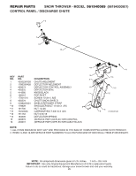
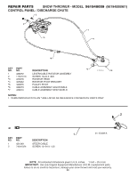
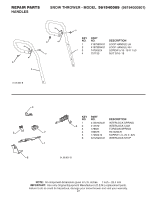
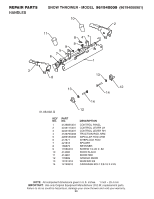
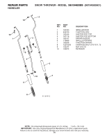
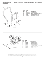
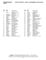
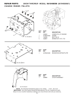
REPAIR PARTS HANDLES SNOW THROWER - MODEL 961940009 (96194000901) 1 4 3 KEY PART NO. NO. DESCRIPTION 1 419797X431 LOWER HANDLE 2 427513X431 PIVOT SUPPORT WELDMENT 3 428867 SCREW 5/16−18 X .750 4 17000616 SCREW 3/8−16 X 1.00 2 4 3 4 4 01-05-013-A 3 2 5 6 7 4 5 41 01.10.007-B KEY NO. 1 2 3 4 5 6 7 PART NO. 182906 178668 180927 184471 175262 178770 183784 DESCRIPTION CONSOLE PANEL HEADLIGHT BEZEL FLOOD HEADLIGHT SHOULDER SCREW 10−24 X .625 SCREW 10−24 X 1.25 WIRE HARNESS BULB NOTE: All component dimensions given in U.S. inches. 1 inch = 25.4 mm IMPORTANT: Use only Original Equipment Manufacturer (O.E.M.) replacement parts. Failure to do so could be hazardous, damage your snow thrower and void your warranty. 30
-
 1
1 -
2
-
3
-
4
-
5
-
6
-
7
-
8
-
9
-
10
-
11
-
12
-
13
-
14
-
15
-
16
-
17
-
18
-
19
-
20
-
21
-
22
-
23
-
24
-
 25
25 -
 26
26 -
 27
27 -
 28
28 -
 29
29 -
 30
30 -
 31
31 -
 32
32 -
 33
33 -
 34
34 -
 35
35 -
36
-
37
-
38
-
39
-
40
 |
 |
30
REPAIR PARTS
SNOW THROWER - MODEL
961940009
(96194000901)
HANDLES
KEY
PART
NO.
NO.
DESCRIPTION
KEY
PART
NO.
NO.
DESCRIPTION
1
2
3
4
5
4
5
7
6
01.10.007-B
NOTE:
All component dimensions given in U.S. inches.
1 inch = 25.4 mm
IMPORTANT:
Use only Original Equipment Manufacturer (O.E.M.) replacement parts.
Failure to do so could be hazardous, damage your snow thrower and void your warranty.
1
182906
CONSOLE PANEL
2
178668
HEADLIGHT BEZEL
3
180927
FLOOD HEADLIGHT
4
184471
SHOULDER SCREW 10
−
24 X .625
5
175262
SCREW 10
−
24 X 1.25
6
178770
WIRE HARNESS
7
183784
BULB
1
2
3
3
4
4
4
4
01-05-013-A
1
419797X431
LOWER HANDLE
2
427513X431
PIVOT SUPPORT WELDMENT
3
428867
SCREW 5/16
−
18 X .750
4
17000616
SCREW 3/8
−
16 X 1.00