Poulan C20H42YT User Manual - Page 21
To Check Brake, To Remove Wheel For Repairs, See Fig., Front Wheel Toe-in/camber, To Replace Motion
 |
View all Poulan C20H42YT manuals
Add to My Manuals
Save this manual to your list of manuals |
Page 21 highlights
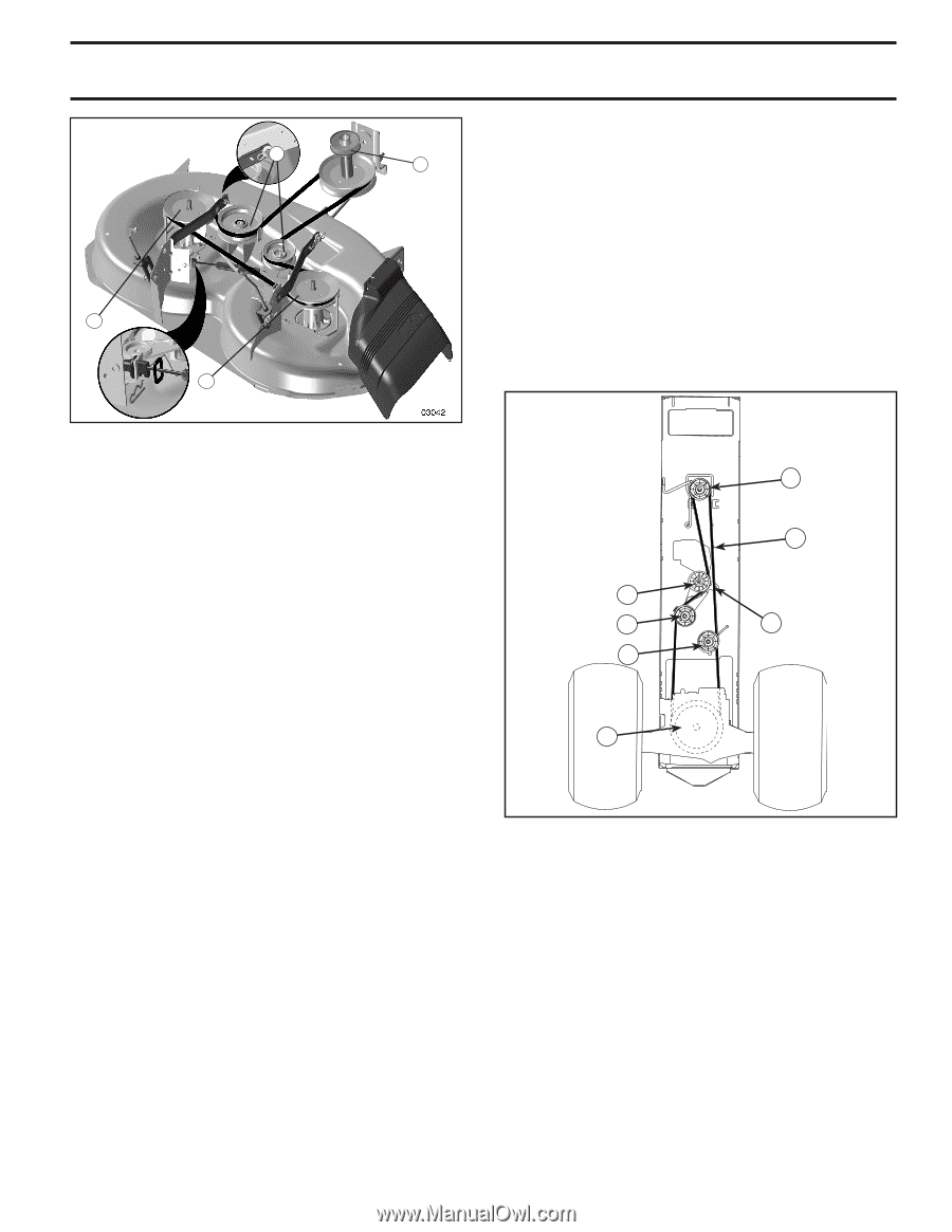
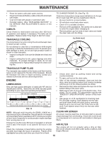
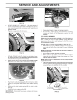
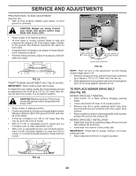
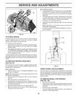
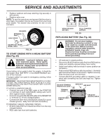
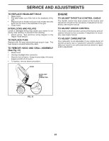
SERVICE AND ADJUSTMENTS S R R BELT INSTALLATION - • Install new belt from tractor rear to front, over the steer- M ing plate (F) and above clutch brake pedal shaft (G). • Pull belt toward front of tractor and roll belt onto engine pulley (E). • Pull belt toward rear of tractor. Carefully work belt down around transmission cooling fan and onto the input pulley (D). Be sure belt is inside the belt keeper. • Install belt on centerspan idler (C). • Install belt through stationary idler (A) and clutching idler (B). • Make sure belt is in all pulley grooves and inside all belt guides and keepers. • Install mower (See "TO INSTALL MOWER" in this section of manual). FIG. 26 TO CHECK BRAKE If tractor requires more than five (5) feet to stop at highest speed in highest gear on a level, dry concrete or paved surface, then brake must be serviced. You may also check brake by: • Park tractor on a level, dry concrete or paved surface, depress brake pedal all the way down and engage parking brake. • Disengage transmission by placing freewheel control in "transmission disengaged" position. Pull freewheel control out and into the slot and release so it is held in the disengaged position. The rear wheels must lock and skid when you try to manually push the tractor forward. If the rear wheels rotate, then the brake needs to be serviced. Contact a qualified service center. TO REPLACE MOTION DRIVE BELT (See Fig. 27) Park the tractor on level surface. Engage parking brake. For assistance, there is a belt installation guide decal on bottom side of left footrest. BELT REMOVAL • Remove mower (See "TO REMOVE MOWER" in this section of manual). NOTE: Observe entire motion drive belt and position of all belt guides and keepers. • Remove belt from stationary idler (A) and clutching idler (B). • Remove belt from centerspan idler (C). • Pull belt slack toward rear of tractor. Carefully remove belt upwards from transmission input pulley and over cooling fan blades (D). • Remove belt downward from engine pulley (E). • Slide belt toward rear of tractor, off the steering plate (F) and remove from tractor. A B C D E F G FIG. 27 FRONT WHEEL TOE-IN/CAMBER Your new tractor front wheel toe-in and camber is set at the factory and is normal. The front wheel toe-in and camber are not adjustable. If damage has occurred to affect the factory set front wheel toe-in or camber, contact a qualified service center. TO REMOVE WHEEL FOR REPAIRS (See Fig. 28) • Block up axle securely. • Remove axle cover, retaining ring and washers to allow wheel removal (rear wheel contains a square key - Do not lose). • Repair tire and reassemble. • On rear wheels only: align grooves in rear wheel hub and axle. Insert square key. 21
-
 1
1 -
2
-
3
-
4
-
5
-
6
-
7
-
8
-
9
-
10
-
11
-
12
-
13
-
14
-
15
-
 16
16 -
 17
17 -
 18
18 -
 19
19 -
 20
20 -
 21
21 -
 22
22 -
 23
23 -
 24
24 -
 25
25 -
 26
26 -
27
-
28
-
29
-
30
 |
 |