Poulan CHDR500C User Manual
Poulan CHDR500C Manual
 |
View all Poulan CHDR500C manuals
Add to My Manuals
Save this manual to your list of manuals |
Poulan CHDR500C manual content summary:
- Poulan CHDR500C | User Manual - Page 1
£moe op d • OWNER'S MANUAL MODEL NO. CHDR500C 5 HP 17 inch Tiller • Assembly • Operation • Customer Responsibilities • Service and Adjustments • Storage • Troubleshooting • Repair Parts Poulan This product has a low emission engine which operates differently from previously built engines. Before you - Poulan CHDR500C | User Manual - Page 2
Read the Owner's Manual carefully. Be thoroughly is generally a warning of trouble. • Stop the engine (motor the engine and make certain all moving parts have stopped. Disconnect the spark plug wire enclosure. • Always refer to the operator's guide instructions for important details if the tiller is - Poulan CHDR500C | User Manual - Page 3
. Should you experience any problems you cannot easily remedy, please contact your nearest authorized service center. We have competent, well-trained technicians and the proper tools to service or repair this unit. Please read and retain this manual. The instructions will enable you to assemble - Poulan CHDR500C | User Manual - Page 4
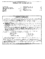
3,13-15 4 5-7 8-12 MAINTENANCE SCHEDULE SERVICE & ADJUSTMENTS STORAGE TROUBLESHOOTING REPAIR PARTS-TILLER 13 15-18 19 20 21-27 been properly assembled, adjusted, operated, and maintained in accordance with the instructions furnished. This Warranty does not apply to any product which has been - Poulan CHDR500C | User Manual - Page 5
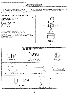
exception of those parts left unassembled for shipping purposes. To ensure safe and proper operation of your tiller, all parts and hardware you POSITION (See Fig. 1) When right or left hand is mentioned in this manual, it means when you are in the operating position (standing behind tiller handles). - Poulan CHDR500C | User Manual - Page 6
down. Insert rear carriage bolt first, with bolt head on L.H. side of tiller and loosely assemble locknut (See Fig. 5). Insert pivot bolt in front part of plate and tighten. Cut down remaining corners of carton and lay panels flat. Lower the handle assembly. Tighten nut on carriage bolt so handle - Poulan CHDR500C | User Manual - Page 7
tire pressure to 20 PSI (1.4 kg/cm2). HANDLE HEIGHT • Handle height may be adjusted to better suit operator. (See 'TO ADJUST HANDLE HEIGHT' in the Service and Adjustments section of this manual). 7 - Poulan CHDR500C | User Manual - Page 8
YOUR TILLER. Compare the illustrations with your tiller to familiarize yourself with the location of various controls and adjustments. Save this manual for future reference. , . • These symbols may appear on your Tiller or in literature supplied with the product. Learn and understand their - Poulan CHDR500C | User Manual - Page 9
OPERATION WEAR YOUR FORESIGHT IS BETTER THAN NO SIGHT The operation of any tiller can result in foreign objects thrown into the eyes, which can result in severe eye damage. Always wear safety glasses or eye shields before starting your tiller and while tilling. We recommend a wide vision safety - Poulan CHDR500C | User Manual - Page 10
approximate capacity see "PRODUCT SPECIFICATIONS" on page 3 of this manual. All oil must meet A.P.I. Service Classification SF, SG or SH. • For cold weather the fuel system of an engine while in storage. To avoid engine problems, the fuel system should be emptied before storage of 30 days or longer - Poulan CHDR500C | User Manual - Page 11
CARBURETOR" in the Service and Adjustments section of this manual. NOTE: If engine does not start, see troubleshooting points. SPARK PLUG CHOKE shaft with shear pins (See 'TINE REPLACEMENT" in the Service and Adjustments section of this manual). If the tiller is unusually overloaded or jammed, the - Poulan CHDR500C | User Manual - Page 12
OPERATION CULTIVATING Cultivating is destroying the weeds between rows to prevent them from robbing nourishment and moisture from the plants. At the same time, breaking up the upper layer of soil crust will help retain moisture in the soil. Best digging depth is 1" to 3" (2.5-7.5 cm). Lower the - Poulan CHDR500C | User Manual - Page 13
full value from the warranty, the operator must maintain tiller as instructed in this manual. Some adjustments will need to be made periodically to properly maintain your tiller. All adjustments in the Service and Adjustments section of this manual should be checked at least once each season. • Once - Poulan CHDR500C | User Manual - Page 14
ENGINE OIL LEVEL" in the Operation section of this manual. AIR CLEANER (See Fig. 20) Service air cleaner cartridge every twenty-five hours, more often . • Remove blower housing and clean as necessary. • Keep cylinder fins free of dirt and chaff. MUFFLER CYLINDER FINS BLOWER HOUSING OIL DRAIN - Poulan CHDR500C | User Manual - Page 15
first. Spark plug type and gap setting is shown in "PRODUCT SPECIFICATIONS" on page 3 of this manual. TRANSMISSION Your transmission is sealed and will only require lubrication if serviced. CLEANING Clean engine. wheels, finish, etc. of all foreign matter. • Keep finished surfaces and wheels free - Poulan CHDR500C | User Manual - Page 16
SERVICE AND ADJUSTMENTS TINE REPLACEMENT (See Figs. 24, 25 and 26) a CAUTION: Tines are sharp. Wear gloves or other protection when han- dling tines. A badly worn - Poulan CHDR500C | User Manual - Page 17
SERVICE AND ADJUSTMENTS TO REMOVE BELT GUARD (See Fig. 27) NOTE: For ease of into engine pulley. BELT MUST BE IN GROOVE ON TOP OF IDLER PULLEY. NOTE POSITION OF BELT TO GUIDES. • Tighten belt guides "A" and "B" and stud "C". • Check belt adjustment as described below. • Replace belt guard. • - Poulan CHDR500C | User Manual - Page 18
altitude or load. If the carburetor does need adjustment, see engine manual. IMPORTANT: NEVER TAMPER WITH THE ENGINE GOVERNOR, WHICH IS FACTORY THE ENGINE-GOVERNED HIGH SPEED NEEDS ADJUSTING, CONTACT YOUR NEAREST AUTHORIZED SERVICE CENTER/ DEPARTMENT, WHICH HAS THE PROPER EQUIPMENT AND EXPERIENCE TO - Poulan CHDR500C | User Manual - Page 19
instructions in the Service and Adjustments section of this manual). • Lubricate as shown in the Customer Responsibilities section of this manual. • Be sure that all nuts, bolts and screws are securely fastened. Inspect moving parts dirt in your gasoline will cause problems. • If possible, store your - Poulan CHDR500C | User Manual - Page 20
TROUBLESHOOTING POINTS PROBLEM Will not start CAUSE 1. Out of fuel. 2. Engine not "CHOKED" properly. 3. screen. 11. Clean/replace muffler. 12. Make necessary adjustments. 13. Contact an authorized service center/department. Engine overheats 1. Low oil level/dirty oil. 2. Dirty engine air screen - Poulan CHDR500C | User Manual - Page 21
c 25 24 22 26 6 26 28 17 27 15 21 14 7 13 KEY PART NO. NO. DESCRIPTION 1 8389J Grip, Handle 2 121248X Bushing, Snap 3 71191008 Screw, 109228X Lever, Lock, Handle 13 150217 Handle o 12 110 9 18 KEY PART NO. NO. 14 159232 15 145821 17 102604X 18 150696 21 159227 22 150744 - Poulan CHDR500C | User Manual - Page 22
3 7 8 6 9 1 39 42 5 16 19 /;" 17 21 20 21 15 1 2 KEY PART NO. NO. 1 73510500 2 10040600 3 73220600 4 74930568 5 154734 6 110111X 7 72110404 8 8700J 9 Clip, Hairpin Guard, Belt Belt, V 26 5 23 24 25 V KEY PART NO. NO. DESCRIPTION 28 104679X 29 12000032 30 159229 31 102384X 32 102141X - Poulan CHDR500C | User Manual - Page 23
Nut, Keps 5/16-18 Bracket, Reinforcement Bolt, Hex 5/16-18 x 1-1/2 Counter Weight, R.H. Washer, Lock 3/8 Nut, Hex 3/8-16 Clip, Hairpin Rivet, Drilled KEY PART NO. NO. 9 102190X 150750 795R 10 DESCRIPTION Tire Rim Tire Valve Engine, Briggs & Stratton Model No. 137202 NOTE: All component dimensions - Poulan CHDR500C | User Manual - Page 24
37 39 49 37 3E 36 50 25 24 Y6r -6( 24 53 25 24 9A 5 44 KEY PART NO. NO. 1 154354 2 150698 3 106211X 4 5020J 5 1370H 6 137335 7 145101 8 , Lock 7/16 Nut, Hex 7/16-20 tearing, Shaft, Ground lye L.H. KEY PART NO. NO. DESCRIPTION 28 106390X 29 102134X 30 150737 31 143008 32 106388X 33 - Poulan CHDR500C | User Manual - Page 25
, Depth Stake Shield, Tine Shield, Side Nut, Hex 5/16-18 Washer, Lock 5/16 Bolt, Carriage 5/16-18 x 1-1/4 Bracket, Shield Tine Shield, Side, Outer R.H. KEY PART NO. NO. 16 73510400 18 72040410 19 102701X 20 73220600 21 102156X 22 74930632 23 4440J 24 72140404 25 6712J 26 109227X 27 102695X428 28 - Poulan CHDR500C | User Manual - Page 26
7 10040600 DESCRIPTION Tine, Outer, L.H. Clevis Pin Tine, Inner, L.H. Clip, Hairpin Assembly, Hub and Plate, L.H. Nut, Hex 3/8-24 Washer, Lock 3/8 KEY PART NO. NO. 8 74610616 9 4460J 10 132728 11 6555J DESCRIPTION Bolt, Hex 3/8-24 x 1 Tine, Outer, R.H. Assembly, Hub and Plate, R.H. Tine, Inner - Poulan CHDR500C | User Manual - Page 27
DESCRIPTION Decal, Logo Decal, Description Decal, Logo Decal, Instruction, Tilling Decal, Shift Indicator Decal, Hand Placement Decal, Caution Decal, Briggs & Stratton Decal, Warning, Rotating Tines Decal, Reverse Decal, 5HP Decal, Warning Till Manual, Owner's (English) Manual, Owner's (French) - Poulan CHDR500C | User Manual - Page 28
Poulan
-
 1
1 -
 2
2 -
 3
3 -
 4
4 -
 5
5 -
 6
6 -
 7
7 -
8
-
9
-
10
-
11
-
12
-
13
-
14
-
15
-
16
-
17
-
18
-
19
-
20
-
21
-
22
-
23
-
24
-
25
-
26
-
27
-
28
 |
 |
£moe
op
d
•
OWNER'S
MANUAL
MODEL
NO.
CHDR500C
5
HP
17
inch
Tiller
•
Assembly
•
Operation
•
Customer
Responsibilities
•
Service
and
Adjustments
•
Storage
•
Troubleshooting
•
Repair
Parts
Poulan
This
product
has
a
low
emission
engine
which
operates
differently
from
previously
built
engines.
Before
you
start
the
engine,
read
and
understand
this
Owner's
Manual.
164744
2.4.98
TR
PRINTED
IN
U.S.A.