Poulan DB24H48YT User Manual - Page 22
To Replace Mower Drive Belt
 |
View all Poulan DB24H48YT manuals
Add to My Manuals
Save this manual to your list of manuals |
Page 22 highlights
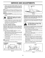
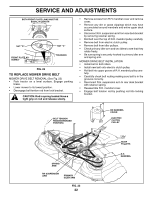
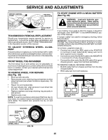
SERVICE AND ADJUSTMENTS BOTH FRONT PLATE LINKS MUST BE EQUAL IN LENGTH 02516 NUT "D" 02517 FRONT PLATE ASSEMBLY NUT "C" TRUNNION FIG. 22 TO REPLACE MOWER DRIVE BELT MOWER DRIVE BELT REMOVAL (See Fig. 23) • Park tractor on a level surface. Engage parking brake. • Lower mower to its lowest position. • Disengage belt tention rod from lock bracket. CAUTION: Rod is spring loaded. Have a tight grip on rod and release slowly. • Remove screws from R.H. mandrel cover and remove cover. • Remove any dirt or grass clippings which may have accumulated around mandrels and entire upper deck surface. • Disconnect R.H.suspension arm from rear deck bracket by removing retainer spring. • Roll belt over the top of R.H. mandrel pulley carefully. • Remove belt from electric clutch pulley. • Remove belt from idler pulleys. • Check primary idler arm and two idlers to see that they rotate freely. • Be sure spring is securely hooked to primary idler arm and spring arm. MOWER DRIVE BELT INSTALLATION • Install belt in both idlers. • Install new belt onto electric clutch pulley. • Roll belt into upper groove of R.H. mandrel pulley carefully. • Carefully check belt routing making sure belt is in the grooves correctly. • Reconnect R.H. suspension arm to rear deck bracket with retainer spring. • Reassemble R.H. mandrel cover. • Engage belt tension rod by pushing rod into locking bracket. BELT TENSION ROD(DISENGAGED POSITION) RH MANDREL COVER ELECTRIC CLUTCH PULLEY SPRING ARM RH SUSPENSION ARM PRIMARY IDLER ARM FIG. 23 22 02513 IDLER PULLEYS R.H. MANDREL
-
 1
1 -
2
-
3
-
4
-
5
-
6
-
7
-
8
-
9
-
10
-
11
-
12
-
13
-
14
-
15
-
16
-
 17
17 -
 18
18 -
 19
19 -
 20
20 -
 21
21 -
 22
22 -
 23
23 -
 24
24 -
 25
25 -
 26
26 -
 27
27 -
28
-
29
-
30
-
31
-
32
 |
 |
