Poulan HDF550J User Manual - Page 5
Unpack, Carton, Install, Handle, Reverse, Depth, Stake, Assembly, Height, Tilling, Width, Operation
 |
View all Poulan HDF550J manuals
Add to My Manuals
Save this manual to your list of manuals |
Page 5 highlights
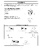
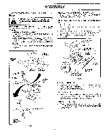
ASSEMBLY UNPACK CARTON & INSTALL HANDLE (See Fig. 2) a CAUTION: Becarefulofexposedstaples when handling or disposing of cartoning material. IMPORTANT: WHEN UNPACKING AND ASSEMBLING TILLER, BE CAREFUL NOT TO STRETCH OR KINK CABLE(S). • Cut cable ties securing handles. • Slowly lift handle assembly up and align handle holes with handle panel hole and slot. • Loosely assemble hardware as shown. Be sure the shorter (3/4" long) hex bolt is assembled in lower hole of handle. Repeat for opposite side. Tighten all hardware securely. • Cut cable ties securing tiller to skid and remove tiller from skid. HANDLE PANEL LOCK NUT WASHER e TILLER HANDLE FLAT WASHER HEX BOLT 5/16-18X1" HEX BOLT 5/16-18X3/4" CABLE TILLER HANDLES HANDLE PANEL BOLTS 0 UPPER REVERSE ROD COTTE PIN O CLEVIS PIN INSTALL REVERSE ROD (See Fig. 2) • Secure upper reverse rod to lower reverse rod using clevis pin. Secure with cotter pin. INSTALL DEPTH STAKE ASSEMBLY (See Fig. 3) • Loosen nut "A" . • Insert stake support between engine bracket halves with stake spring down. • Bolt stake support to engine brackets with bolts, lock washers and nuts. Tighten securely. Tighten nut "A". • Depth stake must move freely. If it does not, loosen support bolt. ENGINE BRACKET HALVES NUT "A" DEPTH STAKE SUPPORT STAKE SPRING Oo o DEPTH STAKE HEX BOLTS, LOCK WASHERS, AND HEX NUTS FIG. 3 SUPPORT BOLT HANDLE HEIGHT • Handle height may be adjusted to better suit operator. (See "HANDLE HEIGHT" in the Service and Adjustments section of this manual). TILLING WIDTH Tilling widthmaybe adjustedtobetterhandle your tilling conditions (See "TINE ARRANGEMENT' in the Service and Adjustments section of this manual). TINE OPERATION • Check tine operation before first use. (See "TINE OPERATION CHECK" in the Service and Adjustments section of this manual). LOWER REVERSE ROD FIG. 2 5
-
 1
1 -
 2
2 -
 3
3 -
 4
4 -
 5
5 -
 6
6 -
 7
7 -
 8
8 -
 9
9 -
 10
10 -
 11
11 -
12
-
13
-
14
-
15
-
16
-
17
-
18
-
19
-
20
-
21
-
22
-
23
-
24
 |
 |
