Poulan PBGT22H54 User Manual - Page 21
Service And Adjustments - lawn tractors
 |
View all Poulan PBGT22H54 manuals
Add to My Manuals
Save this manual to your list of manuals |
Page 21 highlights
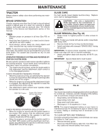
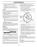
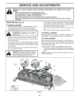
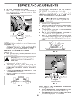
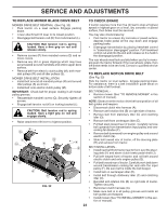
SERVICE AND ADJUSTMENTS WARNING: TO AVOID SERIOUS INJURY, BEFORE PERFORMING ANY SERVICE OR ADJUST- MENTS: • Depress brake pedal fully and set parking brake. • Place attachment clutch in "DISENGAGED" position. • Turn ignition key to "STOP" and remove key. • Make sure the blades and all moving parts have completely stopped. • Disconnect spark plug wire from spark plug and place wire where it cannot come in contact with plug. TRACTOR (See Fig. 27) TO REMOVE MOWER • Place attachment clutch in "DISENGAGED" position. • Lower attachment lift lever to its lowest position. • Disengage belt tension rod (K) from lock bracket (L). • From right side of mower, disconnect anti-sway bar (S) from right rear mower bracket (D) - remove retainer spring and washer and pull mower toward you until the bar falls from the hole in bracket. • Turn tractor steering wheel to the left as far as it will go. • Slide mower out from under right side of tractor. CAUTION: Belt tension rod is spring loaded. Have a tight grip on rod and release slowly. • Remove mower belt from electric clutch pulley (M). • Disconnect front link (E) from mower - remove retainer spring and washer. • Go to either side of mower and disconnect mower suspension arm (A) from chassis and rear lift link (C) from rear mower bracket (D) - remove retainer springs and washers. • Go to other side of mower and disconnect the suspension arm and rear lift link. CAUTION: After rear lift links are disconnected, the attachment lift lever will be spring loaded. Have a tight grip on lift lever when changing position of the lever. TO INSTALL MOWER Follow procedure described in "INSTALL MOWER AND DRIVE BELT" in the Assembly section of this manual. TO LEVEL MOWER Make sure tires are properly inflated to the PSI shown on tires. If tires are over or under inflated, it may affect the appearance of your lawn and lead you to think the mower is not adjusted properly. VISUAL SIDE-TO-SIDE ADJUSTMENT (See Fig. 28) • With all tires properly inflated and if your lawn appears unevenly cut, determine which side of mower is cutting lower. NOTE: As desired, you can raise the low side of mower or lower the high side. L K B M A F E H S C D FIG. 27 21
-
 1
1 -
2
-
3
-
4
-
5
-
6
-
7
-
8
-
9
-
10
-
11
-
12
-
13
-
14
-
15
-
 16
16 -
 17
17 -
 18
18 -
 19
19 -
 20
20 -
 21
21 -
 22
22 -
 23
23 -
 24
24 -
 25
25 -
 26
26 -
27
-
28
-
29
-
30
-
31
-
32
 |
 |