Poulan PD20PH42STA User Manual - Page 7
To Drive Tractor Off Skid See Op - mowers
 |
View all Poulan PD20PH42STA manuals
Add to My Manuals
Save this manual to your list of manuals |
Page 7 highlights
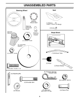
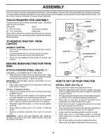
ASSEMBLY SEAT SEAT PAN 2466 SHOULDER BOLT FLAT WASHER ADJUSTMENT KNOB 02464 FIG. 2 CHECK BATTERY (See Fig. 3) • Lift seat pan to raised position. • If this battery is put into service after month and year indicated on label (label located between terminals) charge battery for minimum of one hour at 6-10 amps. (See "BATTERY" in Maintenance section of this manual for charging instructions). SEAT PAN LABEL 02602 FIG. 3 NOTE: You may now roll or drive your tractor off the skid. Follow the appropriate instruction below to remove the tractor from the skid. TO ROLL TRACTOR OFF SKID (See Operation section for location and function of controls) • Press lift lever plunger and raise attachment lift lever to its highest position. • Release parking brake by depressing brake pedal. • Place freewheel control in "transmission disengaged position" (See "TO TRANSPORT" in the Operation section of this manual). • Roll tractor forward off skid. • Remove banding holding the deflector shield up against tractor. TO DRIVE TRACTOR OFF SKID (See Operation section for location and function of controls) WARNING: Before starting, read, understand and follow all instructions in the Operation section of this manual. Be sure tractor is in a well-ventilated area. Be sure the area in front of tractor is clear of other people and objects. • Be sure all the above assembly steps have been com- pleted. • Check engine oil level and fill fuel tank with gasoline. • Place freewheel control in "transmission engaged" position (see "TO TRANSPORT" in Operation section of this manual). • Sit on seat in operating position, depress brake pedal and set the parking brake. • Place motion control lever in neutral (N) position. • Press lift lever plunger and raise attachment lift lever to its highest position. • Start the engine.After engine has started, move throttle control to idle position. • Release parking brake. • Slowly move the motion control lever forward and slowly drive tractor off skid. • Apply brake to stop tractor, set parking brake and place motion control lever in neutral position. • Turn ignition key to "STOP" position. Continue with the instructions that follow. ASSEMBLE GAUGE WHEELS TO MOWER DECK (See Fig. 4) The gauge wheels are designed to keep the mower deck in proper position when operating mower. Be sure they are properly adjusted to ensure optimum mower performance. • Slide gauge wheel bar down into bracket channel, Be sure that gauge wheel bar aligning holes are on top. Assemble gauge wheels as shown using shoulder bolts, 3/8 washers and 3/8-16 center locknuts and tighten securely. • Adjust gauge wheels before operating mower. See "TO ADJUST GAUGE WHEELS" in the Operation section of this manual. RETAINER SPRING PIN SHOULDER BOLT ADJUSTING BAR 02115 GAUGE WHEEL 3/8 WASHER 3/8-16 CENTER LOCKNUT FIG. 4 7
-
 1
1 -
 2
2 -
 3
3 -
 4
4 -
 5
5 -
 6
6 -
 7
7 -
 8
8 -
 9
9 -
 10
10 -
 11
11 -
 12
12 -
13
-
14
-
15
-
16
-
17
-
18
-
19
-
20
-
21
-
22
-
23
-
24
-
25
-
26
-
27
-
28
-
29
-
30
-
31
-
32
-
33
-
34
-
35
-
36
-
37
-
38
-
39
-
40
-
41
-
42
-
43
-
44
-
45
-
46
-
47
-
48
 |
 |
