Poulan PPB330 User Manual - Page 9
Assembly - manual
 |
View all Poulan PPB330 manuals
Add to My Manuals
Save this manual to your list of manuals |
Page 9 highlights
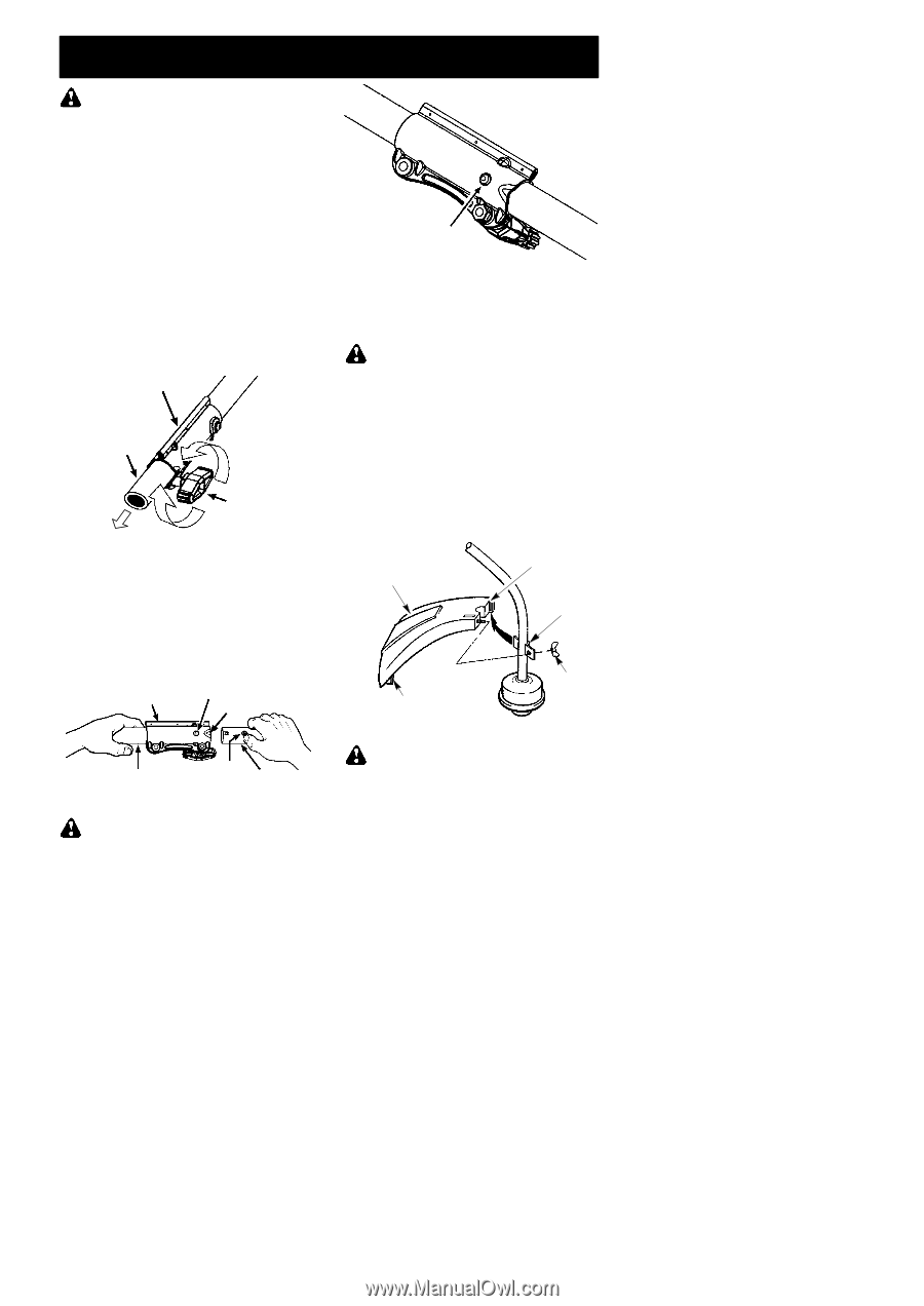
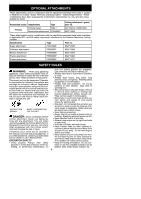
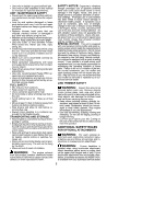
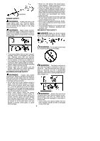
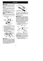
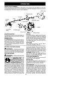
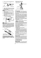
ASSEMBLY WARNING: If received assembled, repeat all steps to ensure your unit is properly assembled and all fasteners are secure. Examine parts for damage. Do not use damaged parts. NOTE: If you need assistance or find parts missing or damaged, call 1-800-554-6723. It is normal for the fuel filter to rattle in the empty fuel tank. Finding fuel or oil residue on muffler is normal due to carburetor adjustments and testing done by the manufacturer. INSTALLING TRIMMER ATTACHMENT CAUTION: When installing trimmer attachment, place the unit on a flat surface for stability. 1. Loosen the coupler by turning the knob counterclockwise. Coupler Shipping protector LOOSEN Knob TIGHTEN 2. Remove shipping protector from coupler. 3. Remove the shaft cap from the trimmer attachment (if present). 4. Position locking/release button of attach- ment into guide recess of coupler. 5. Push the attachment into the coupler until the locking/release button snaps into the primary hole. 6. Before using the unit, tighten the knob se- curely by turning clockwise. Coupler Primary Hole Guide Recess Upper Shaft Locking/ Release Attachment Button WARNING: Make sure the locking/ release button is locked in the primary hole and the knob is securely tightened before operating the unit. All attachments are designed to be used in the primary hole unless otherwise stated in the applicable attachment instruction manual. Using the wrong hole could lead to serious injury or damage to the unit. Locking/Release Button in Primary Hole For assembly of optional attachments (see list on page 11), refer to the ASSEMBLY section of the applicable attachment instruction manual. ATTACHING SHIELD WARNING: The shield must be prop- erly installed. The shield provides partial protection from the risk of thrown objects to the operator and others and is equipped with a line limiter blade which cuts excess line to the proper length. The line limiter blade (on underside of shield) is sharp and can cut you. For proper orientation of shield, see KNOW YOUR TRIMMER illustration in OPERATION section. 1. Remove wing nut from shield. 2. Insert bracket into slot as shown. 3. Pivot shield until bolt passes through hole in bracket. 4. Securely tighten wing nut onto bolt. Slot Shield Bracket Line limiter blade Wing nut ADJUSTING THE ASSIST HANDLE WARNING: When adjusting the assist handle, be sure it remains above the safety label and below the mark or arrow on the shaft. 1. Loosen wing nut on handle. 2. Rotate the handle on the shaft to an up- right position; retighten wing nut. 9
-
 1
1 -
2
-
3
-
 4
4 -
 5
5 -
 6
6 -
 7
7 -
 8
8 -
 9
9 -
 10
10 -
 11
11 -
 12
12 -
 13
13 -
 14
14 -
15
-
16
-
17
-
18
-
19
 |
 |