Poulan PPB335 User Manual - Page 14
Service And Adjustments, Inspect And Clean Unit - pro
 |
View all Poulan PPB335 manuals
Add to My Manuals
Save this manual to your list of manuals |
Page 14 highlights
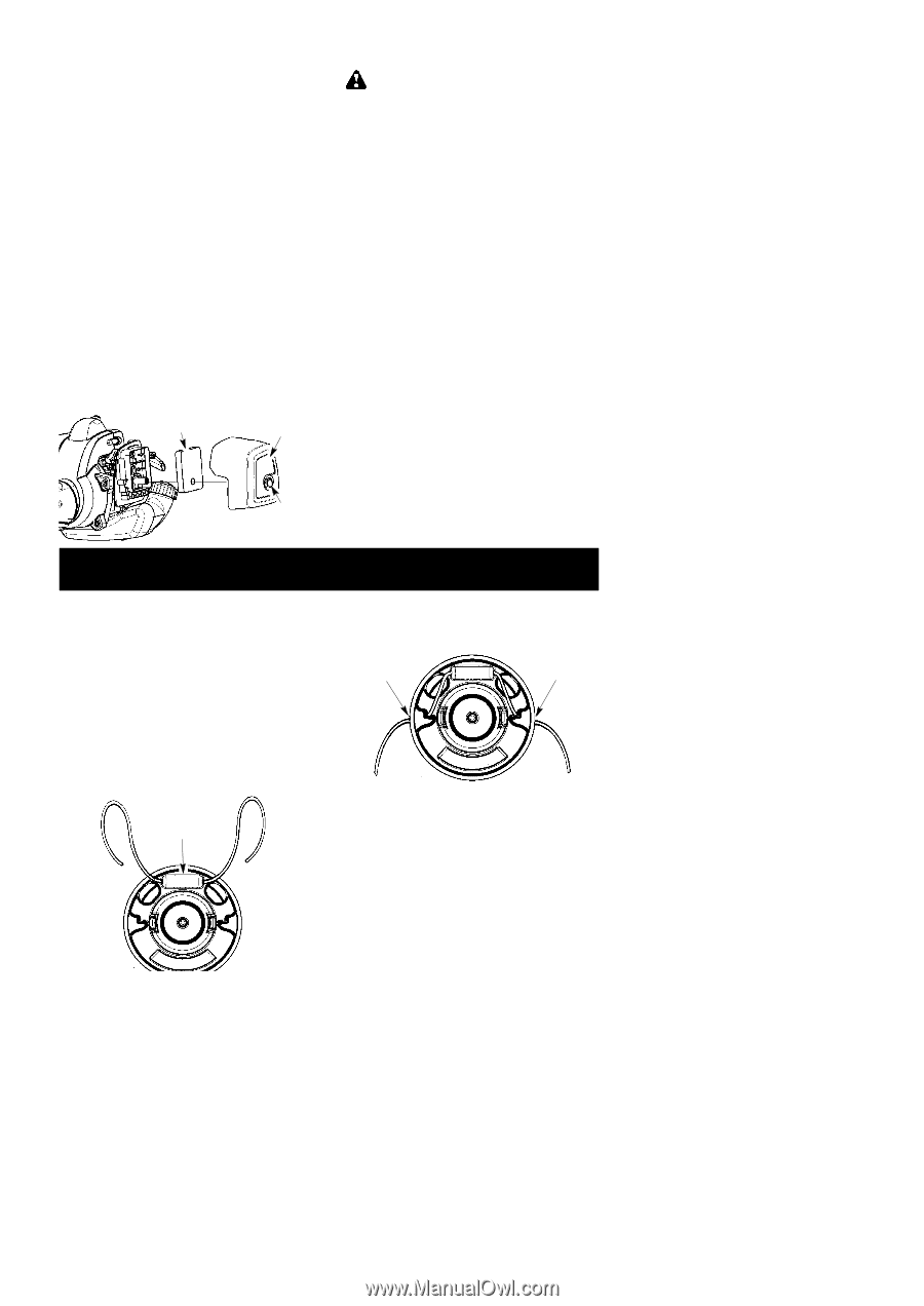
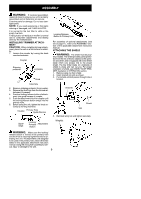
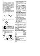
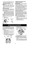
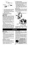
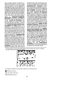
S Fuel Tank -- Discontinue use of unit if fuel tank shows signs of damage or leaks. S Debris Shield -- Discontinue use of unit if debris shield is damaged. INSPECT AND CLEAN UNIT AND DECALS S After each use, inspect complete unit for loose or damaged parts. Clean the unit and decals using a damp cloth with a mild detergent. S Wipe off unit with a clean dry cloth. CLEAN AIR FILTER A dirty air filter decreases engine performance and increases fuel consumption and harmful emissions. Always clean after every 5 hours of operation. 1. Clean the cover and the area around it to keep dirt from falling into the carburetor chamber when the cover is removed. 2. Loosen bolt with a 5/16 inch (8 mm) socket wrench. Remove air filter cover and air filter. NOTE: To avoid creating a fire hazard or producing harmful evaporative emissions, do not clean filter in gasoline or other flammable solvent. 3. Wash the filter in soap and water. 4. Allow filter to dry. 5. Replace parts. Air filter Air filter cover INSPECT MUFFLER AND SPARK ARRESTING SCREEN WARNING: The muffler on this prod- uct contains chemicals known to the State of California to cause cancer. As your unit is used, carbon deposits build up on the muffler and spark arresting screen and must be removed to avoid creating a fire hazard or affecting engine performance. For normal homeowner use, the muffler and spark arresting screen will not require any service. After 50 hours of use, we recommend that your muffler be serviced or replaced by an authorized service dealer. REPLACE SPARK PLUG Replace the spark plug each year to ensure the engine starts easier and runs better. Inspect spark plug every 25 hours of usage. Clean and/or replace as necessary. Set spark plug gap at 0.025 inch (0.6 mm). Ignition timing is fixed and nonadjustable. NOTE: This spark ignition system complies with the Canadian standard ICES--002. 1. Twist, then pull off spark plug boot. 2. Remove spark plug from cylinder and discard. 3. Replace with Champion RCJ-6Y spark plug and tighten securely with a 3/4 inch (19 mm) socket wrench. 4. Reinstall the spark plug boot. Bolt SERVICE AND ADJUSTMENTS REPLACING THE LINE For unit to operate properly, the cutting line should be replaced when line becomes worn to less than 3 inches (7.5 cm) in length from the edge of the line exit tunnels on each side of the cutting head. 1. Remove and discard worn line before installing new line. 2. Use only 0.115 inch (3 mm) diameter Poulan PRO brand cut length line. 3. Insert one end of the line through the positioning tunnel. 4. Continue to feed line through tunnel until line is centered (leaving equal amounts on each side). See illustration below. Positioning tunnel 5. Insert ends of line one at a time through the line exit tunnels. 6. Pull the line and make sure the line is extended fully through the tunnels. Line exit tunnel Line exit tunnel 7. Correctly installed line will be the same length on both ends. REPLACING THE CUTTING HEAD 1. Align hole in the dust cup with the hole in the side of the gearbox by rotating the dust cup. 2. Insert a small screwdriver into aligned holes. This will keep the shaft from turning while removing and installing trimmer head. 14
-
 1
1 -
2
-
3
-
4
-
5
-
6
-
7
-
8
-
 9
9 -
 10
10 -
 11
11 -
 12
12 -
 13
13 -
 14
14 -
 15
15 -
 16
16 -
 17
17 -
 18
18
 |
 |