Poulan PR100 Owner Manual - Page 7
Controls & Features
 |
View all Poulan PR100 manuals
Add to My Manuals
Save this manual to your list of manuals |
Page 7 highlights
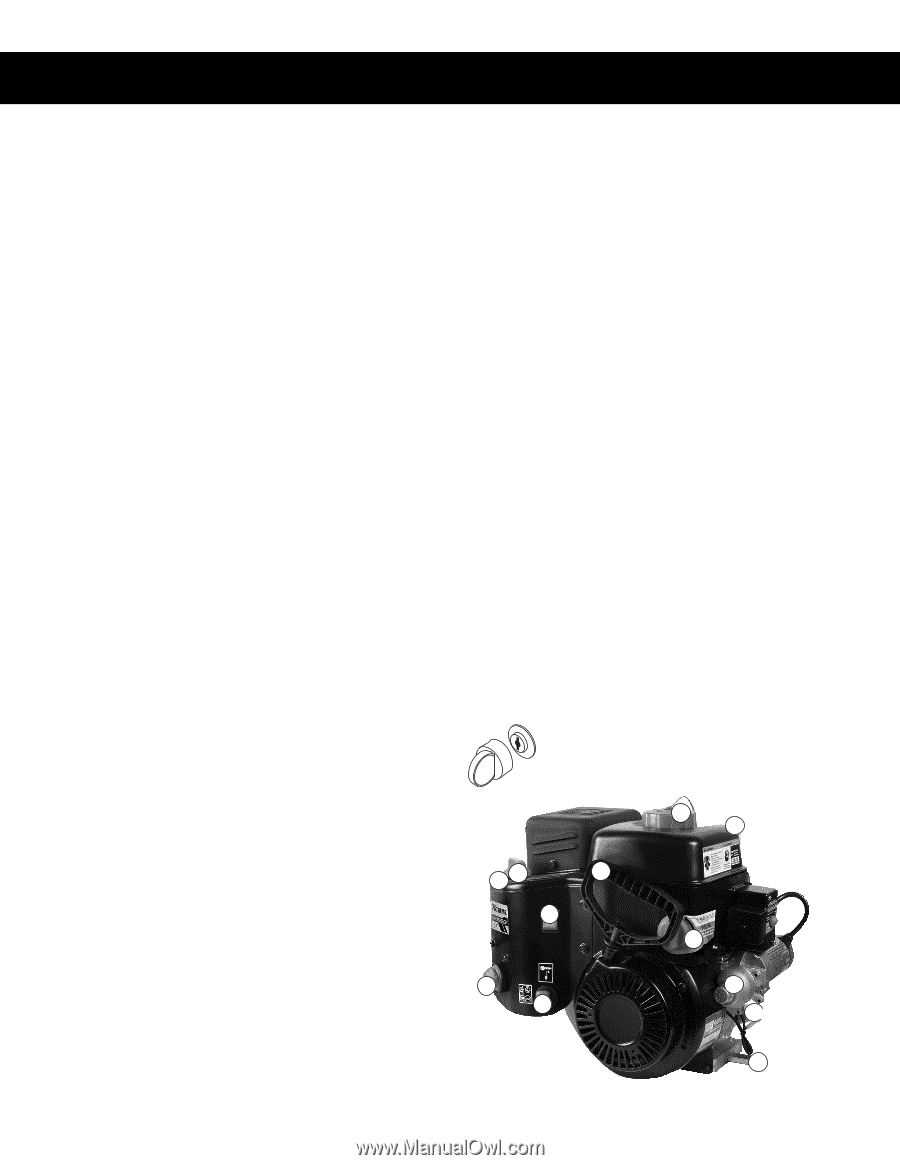
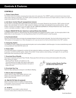
Controls & Features CONTROLS 1. Choke Control Knob The Choke Control Knob opens and closes the choke valve in the carburetor. The "START" position enriches the fuel mixture which allows easier starting a cold engine. The "RUN" position provides the correct fuel mixture once engine warms up. Never try to shut the engine down using the Choke Control Knob. 2. Idle-Down Control Ring (if equipped) (not shown) The Idle-Down Control Ring sets engine speed from high-speed to low-speed. Rotate the ring clockwise, "RUN" position for highspeed. This control MUST be set in the "RUN" position for starting a cold engine. By rotating the ring counterclockwise, "IDLE" position, will allow your engine to run at low-speed. DO NOT OPERATE EQUIPMENT IN THE IDLE POSITION. Note: the idle-down control is intended to be either in "RUN" or "IDLE" positions only. 3. Engine RUN/STOP Rocker Switch (or optional Rotary Key Switch) The Engine Rocker Switch (or optional Rotary Key Switch) enables and disables the ignition system. Turn the engine switch to the RUN position to start the engine. Turn the Engine Rocker Switch to the STOP position to stop the engine. 4. Fuel Control Knob The Fuel Control Knob opens and closes the passage between the fuel tank and carburetor. The Fuel Control Knob must be in the "ON" position for the engine to run. When the engine is not in use, be sure to turn the Fuel Control Knob to the "OFF" position. 5. Safety Key Switch The Safety Key Switch enables the engine electrical system and must be installed to start the engine. On some models this key switch is incorporated with the RUN/STOP switch, #3. 6. Primer Bulb The Primer Bulb system is designed to enrichen the fuel mixture for starting a cold engine. DO NOT over prime the fuel system. To properly use the Primer Bulb system, depress Primer Bulb 3 times maximum when starting a cold engine. Do not use Primer Bulb system when attempting to start a warm engine. 7. Oversized Recoil Handle The engine is started by pulling the Recoil Handle. Always grip firmly and have your body positioned properly when pulling. When starting the engine: · Slowly pull Recoil Handle until resistance is felt. OFF · Then pull firmly the full length of thReUNrope to start engine. · Never wrap thumb around Recoil Handle in the eFvUenEtLof ON engine kick-back. START 3X's MAX Optional combined Engine Run/Stop and Safety Key Switch (3 & 5) 8. Oversized Gas Cap Allows for easy opening and closing for more efficient refueling. 8 10 9. Electric Start (if equipped) Used to start the engine with 120VAC extension cord. Always use correct size extension cord to prevent electric starter damage. 10. High Oil Fill Tube (if equipped) Allows convenient location for adding oil during the life of the engine. Check oil level with lower oil fill plug (10A) per owner's manual instructions. 11. Oil Drain The oil drain can be located on either side and on some models extend out below the recoil housing. rev. 01/04/16 2 1 7 3 PGH45600 6 5 4 9 10 A 11 Snow Engine Manual 4
-
 1
1 -
 2
2 -
 3
3 -
 4
4 -
 5
5 -
 6
6 -
 7
7 -
 8
8 -
 9
9 -
 10
10 -
 11
11 -
 12
12 -
13
-
14
-
15
-
16
-
17
-
18
-
19
-
20
-
21
-
22
-
23
-
24
-
25
-
26
-
27
-
28
-
29
-
30
-
31
 |
 |