Poulan PR270 Owner Manual - Page 6
Check Tire Pressure, Install Discharge Chute / Chute Rotator Head, See Fig. 4 And 5, Install Chute
 |
View all Poulan PR270 manuals
Add to My Manuals
Save this manual to your list of manuals |
Page 6 highlights
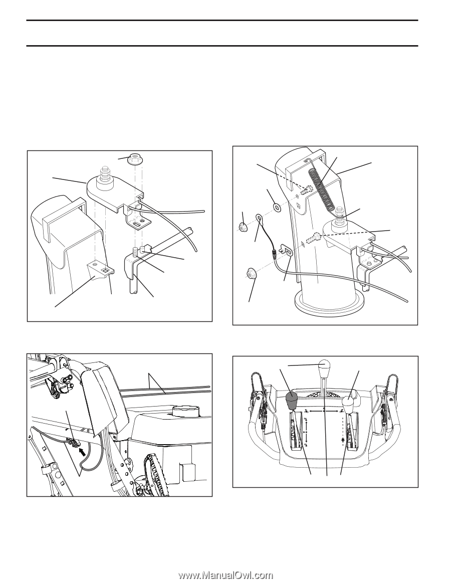
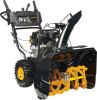
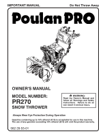
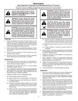
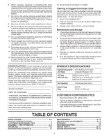
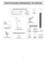
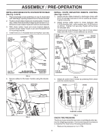
ASSEMBLY / PRE-OPERATION INSTALL DISCHARGE CHUTE / CHUTE ROTATOR HEAD (See Fig. 4 and 5) 1. Place discharge chute assembly on top of chute base with discharge opening toward front of snow thrower. 2. Position chute rotator head over chute bracket. If necessary, rotate chute assembly to align square and pin on underside of chute rotator head with holes in chute bracket. 3. With chute rotator head and chute bracket aligned, position chute rotator head on pin and threaded stud of mounting bracket. 4. Install locknut on threaded stud and tighten securely. CHUTE ROTATOR HEAD LOCKNUT PIN THREADED STUD CHUTE BRACKET ROTATOR HEAD ALIGN BEFORE MOUNTING TIGHTENING LOCKNUT BRACKET FIG. 4 5. Secure cables to the lower handle using the double clip. ROTATOR CABLES INSTALL CHUTE DEFLECTOR REMOTE CONTROL (See Figs. 6 and 7) 1. Install remote cable bracket to discharge chute with 5/16-18 carriage bolt and 5/16-18 locknut as shown. Tighten securely. 2. Install remote cable eyelet to chute deflector with 1/4-20 shoulder bolt, nylon washer and 1/4-20 locknut as shown. Tighten nut securely. Eyelet will be loose on shoulder bolt. 3. Install spring hooks between hex nuts on chute rotator head and into hole in chute deflector as shown. 1/4-20 SHOULDER BOLT SPRING CHUTE DEFLECTOR NYLON WASHER 1/4-20 LOCKNUT HOOK BETWEEN HEX NUTS ON CHUTE ROTATOR HEAD 5/16-18 CARRIAGE BOLT CABLE EYELET REMOTE CABLE BRACKET 5/16-18 LOCKNUT FIG. 6 4. Install all control lever knobs by pressing them down onto the control levers. KNOB KNOB DOUBLE CLIP ROTATOR CABLES FIG. 5 CONTROL LEVER FIG. 7 CHECK TIRE PRESSURE The tires on your snow thrower were overinflated at the factory for shipping purposes. Correct and equal tire pressure is important for best snow throwing performance. • Reduce tire pressure to 14-17 PSI. 6
-
 1
1 -
 2
2 -
 3
3 -
 4
4 -
 5
5 -
 6
6 -
 7
7 -
 8
8 -
 9
9 -
 10
10 -
 11
11 -
 12
12 -
13
-
14
-
15
-
16
-
17
-
18
-
19
-
20
-
21
-
22
-
23
-
24
-
25
-
26
-
27
-
28
-
29
-
30
-
31
-
32
-
33
-
34
-
35
-
36
-
37
-
38
-
39
-
40
-
41
-
42
-
43
-
44
 |
 |