ProForm 1280s Interactive Trainer Elliptical English Manual - Page 9
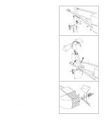
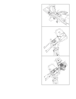
Be careful to avoid pinching, the wire harnesses., Do not tighten the Tapered Button Screws yet.
 |
View all ProForm 1280s Interactive Trainer Elliptical manuals
Add to My Manuals
Save this manual to your list of manuals |
Page 9 highlights
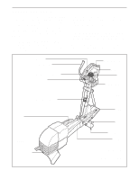
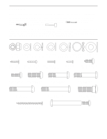
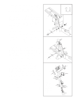
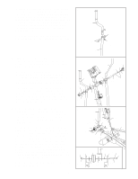
10. Identify the Left Pedal (13). Attach the Left Pedal to the left Flex Bar (14) with an M10 x 35mm Carriage Bolt (20), an M10 Washer (99), an M10 Split Washer (144), and a Pedal Knob (15) as shown. Note: The Left Pedal can be attached in any of five positions (see HOW TO ADJUST THE PEDALS on page 11). Attach the Right Pedal (12) in the same way. Make sure that both Pedals are in the same position. See step 7. Tighten the four M8 x 43mm Button Bolts (50). 10 14 11. Loosen the eight indicated screws (A) in the Center 11 Handlebar (63). Attach the Center Handlebar (63) to the Upright (2) with eight M6 x 16mm Tapered Button Screws (107). Do not tighten the Tapered Button Screws yet. Retighten the eight screws (A) in the Center Handlebar (63). 20 12 13 144 99 15 63 A 12. See step 13. Remove the six M4 x 16mm Screws (66) and the Left and Right Handlebar Covers (109, 110) from the Console (5). Attach the CD Holder (114) to the Console (5) with two M4 x 12mm Screws (84) as shown. While another person holds the Console (5) in the position shown, connect the wire harness on the Console to the Upper Wire Harness (86). Insert the excess wire harness down into the Upright (2). Attach the Console (5) to the Upright (2) with four M4 x 12mm Screws (84). Be careful to avoid pinching the wire harnesses. 107 107 12 84 2 114 5 84 86 2 Wire Harness 9
-
 1
1 -
2
-
3
-
 4
4 -
 5
5 -
 6
6 -
 7
7 -
 8
8 -
 9
9 -
 10
10 -
 11
11 -
 12
12 -
 13
13 -
 14
14 -
15
-
16
-
17
-
18
-
19
-
20
-
21
-
22
-
23
-
24
-
25
-
26
-
27
-
28
 |
 |
