ProForm 1500 Sel User Manual - Page 8
into the Latch Housing Cover and the Latch Housing
 |
View all ProForm 1500 Sel manuals
Add to My Manuals
Save this manual to your list of manuals |
Page 8 highlights
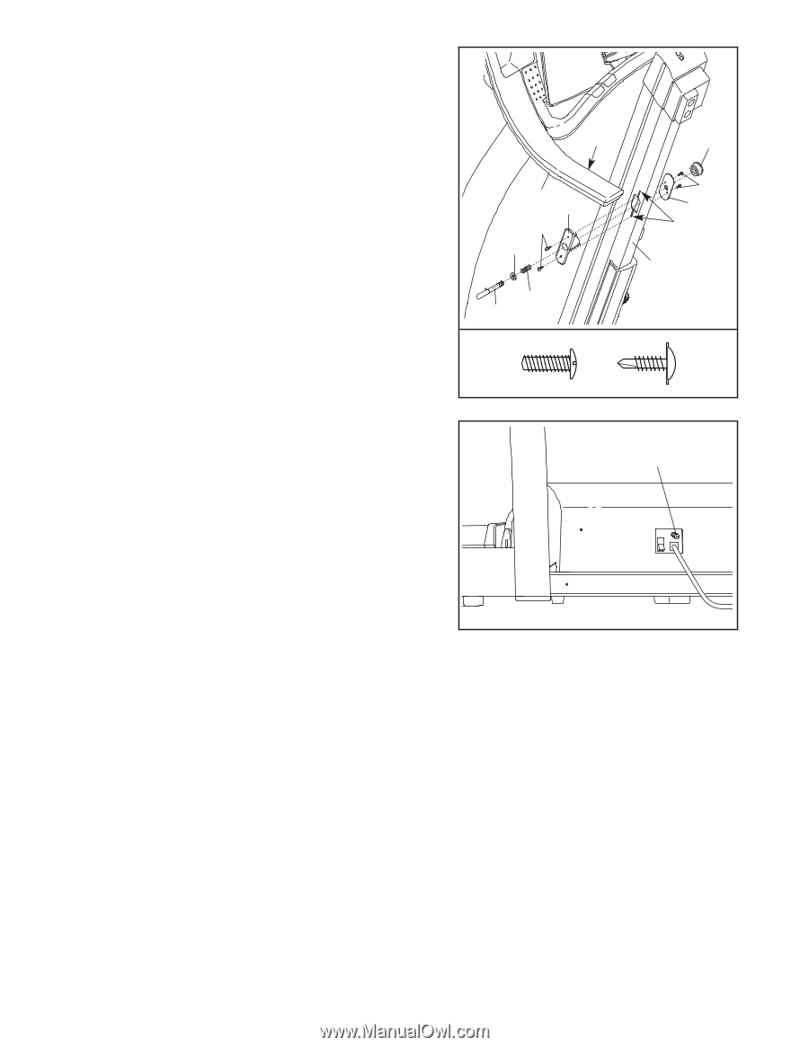
3. With the help of a second person, raise the treadmill Frame (55). Hold the Latch Housing (68) and the Latch Housing Cover (5) against the sides of the Frame as shown. Loosely thread the two blunt-tipped 1/2" Screws (132) into the Latch Housing Cover and the Latch Housing as shown. Do not tighten the Screws yet. Remove the knob from the pin. Make sure that the collar and the spring are on the pin. The collar should be on the side of the spring shown. Insert the pin into the Latch Housing (68), and tighten the knob back onto it. Align the pin with the hole in the Left Handgrip (140) by sliding the Latch Housing (68) up or down. Make sure that the pin can be inserted fully into the hole. Hold the Latch Housing in place as you tighten two 1/2" Tek Screws (114) into the Latch Housing and the Frame (55). Then, tighten the 1/2" Screws (132). Note: It may be necessary to pull on the knob to access and tighten the Screws. 3 Hole 140 68 114 Collar Spring Pin 132 Knob 132 5 Small Holes 55 114 4. Note the location of the 75 ohm antenna terminal on the treadmill. For the television to operate properly, an 4 antenna, a CATV cable, or a VCR must be connected to the 75 ohm antenna terminal (see page 9). 75 Ohm Antenna Terminal 5. Make sure that all parts are properly tightened before you use the treadmill. Place a mat beneath the treadmill to protect the floor or carpet. Note: Extra hardware may be included. Keep the included allen wrench in a secure place; the allen wrench is used to adjust the walking belt (see page 23). For your benefit, we recommend that you familiarize yourself with the TROUBLESHOOTING section on pages 23 and 24. 8
-
 1
1 -
2
-
 3
3 -
 4
4 -
 5
5 -
 6
6 -
 7
7 -
 8
8 -
 9
9 -
 10
10 -
 11
11 -
 12
12 -
 13
13 -
14
-
15
-
16
-
17
-
18
-
19
-
20
-
21
-
22
-
23
-
24
-
25
-
26
-
27
-
28
-
29
-
30
 |
 |