ProForm 225c English Manual - Page 4
Assembly - parts
 |
View all ProForm 225c manuals
Add to My Manuals
Save this manual to your list of manuals |
Page 4 highlights
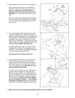
ASSEMBLY Place all parts of the stepper in a cleared area and remove the packing materials. Do not dispose of the packing materials until assembly is completed. Assembly requires the included allen wrench , a phillips screwdriver , two adjustable wrenches and a rubber mallet . 1. Attach the Stabilizer (8) to the Base (2) with two M10 x 82mm Carriage Bolts (24) and two M10 1 Locknuts (15). Slide the Upright (1) onto the threaded bolts in the Base (2). Make sure that the Upright is angled in the direction shown. Attach the Upright with four M10 Locknuts (15). 8 15 1 2 15 24 2. Refer to drawing 2a. Identify the Right Pedal Leg (7) 2a and the Left Pedal Leg (6). Note the positions of the welded tubes and the Magnet (26). Refer to drawing 2b. Attach a Pedal (11) to each Pedal Leg (6, 7) with four M4 x 10mm Screws (28). 6 Tubes 26 2b 11 7 6, 7 3. Slide a Metal Cap (30) onto the indicated shaft on the Base (2). Make sure that the open side of the 3 Metal Cap is facing the Base. Next, apply grease to the shaft on the Base (2). Apply grease to the Pedal Leg Bushings (16) that 6 are in the Right Pedal Leg (7). Slide the Right Pedal Leg (7) onto the shaft on the Base (2). Tap a 3/4Ó Axle Cap (17) onto the shaft. Repeat this step to attach the Left Pedal Leg (6). 28 Apply Grease to Shaft 2 30 Apply Grease 7 16 17 4
-
 1
1 -
 2
2 -
 3
3 -
 4
4 -
 5
5 -
 6
6 -
 7
7 -
 8
8 -
 9
9 -
 10
10 -
11
-
12
 |
 |
