ProForm 395p Instruction Manual - Page 10
track of which screws were removed from which holes.
 |
View all ProForm 395p manuals
Add to My Manuals
Save this manual to your list of manuals |
Page 10 highlights
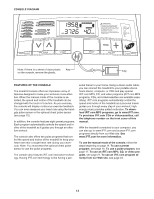
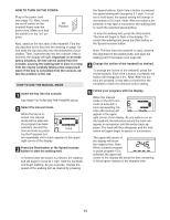
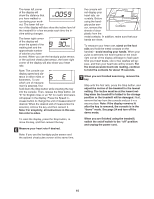
7. Press the Upright Wire (42) into the slot in the underside 7 of the Console Base (47) in the indicated area. Cover the Upright Wire with the Right Grip Plate (36). Be careful not to pinch the Upright Wire. Tighten three 3/4" Screws (2) into the Right Grip Plate and the Console Base. 47 Slot 42 36 2 8. Attach the Storage Latch (29) and the Latch Spacer (44) 8 to the left Upright (69) with two 3/4" Screws (2) as shown. Do not overtighten the Screws. 69 29 44 2 9. Make sure that all parts are properly tightened before you use the treadmill. Note: Extra hardware may be included. Keep the included hex keys in a secure place; the large hex key is used to adjust the walking belt (see page 28). To protect the floor or carpet, place a mat under the treadmill. If you purchase the optional chest pulse sensor (see page 24), follow the steps below to install the receiver included with the chest pulse sensor. 1. Make sure that the power cord is unplugged. Remove 1 the indicated screws from the console base (A). Important: The screws may be different lengths. Keep track of which screws were removed from which holes. A Screws 10
-
 1
1 -
2
-
3
-
4
-
 5
5 -
 6
6 -
 7
7 -
 8
8 -
 9
9 -
 10
10 -
 11
11 -
 12
12 -
 13
13 -
 14
14 -
 15
15 -
16
-
17
-
18
-
19
-
20
-
21
-
22
-
23
-
24
-
25
-
26
-
27
-
28
-
29
-
30
-
31
-
32
-
33
-
34
-
35
 |
 |
