ProForm 495 Pi Treadmill English Manual - Page 9
Screws 48 into the Right Grip Plate and the Console
 |
View all ProForm 495 Pi Treadmill manuals
Add to My Manuals
Save this manual to your list of manuals |
Page 9 highlights
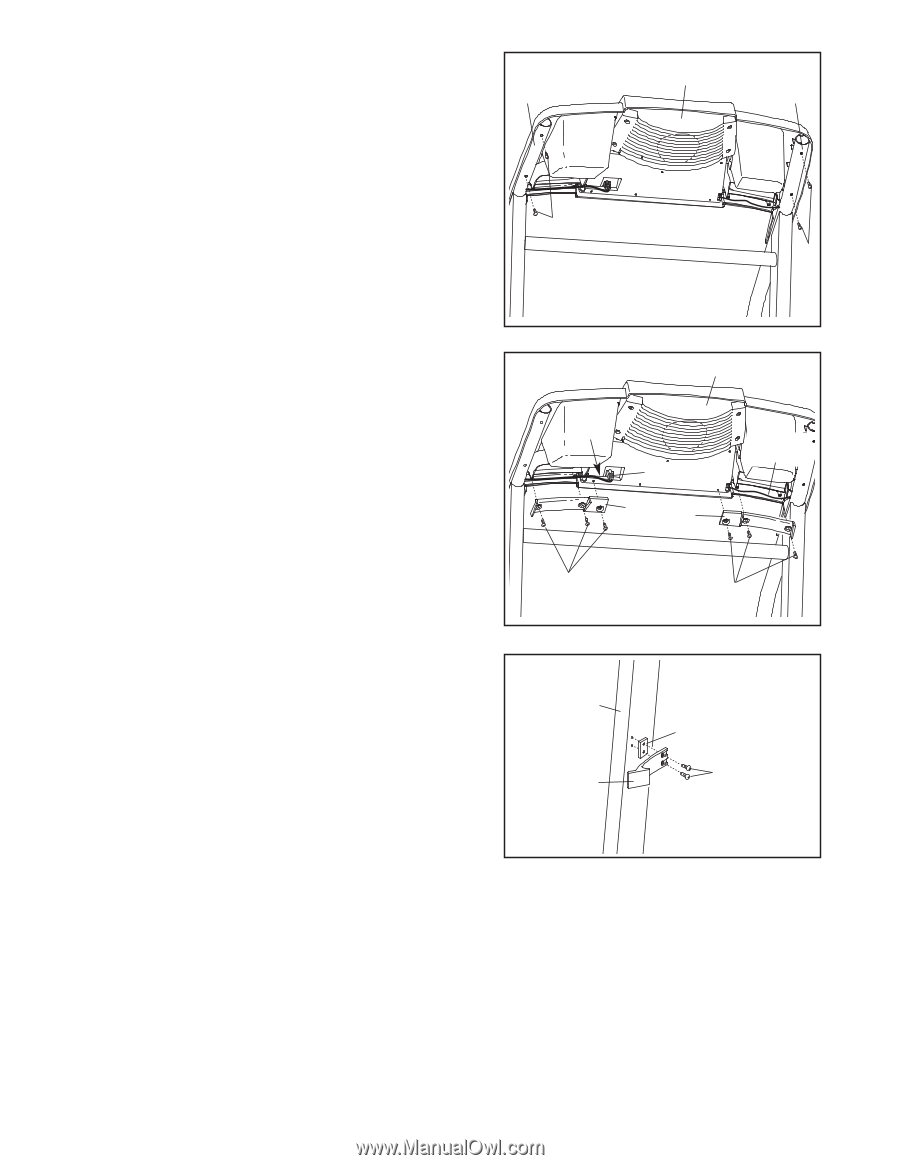
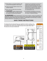
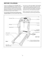
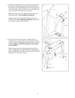
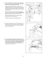
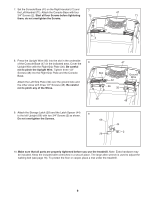
7. Set the Console Base (47) on the Right Handrail (72) and the Left Handrail (71). Attach the Console Base with four 7 3/4" Screws (2). Start all four Screws before tightening 72 them; do not overtighten the Screws. 47 71 2 2 8. Press the Upright Wire (42) into the slot in the underside 8 of the Console Base (47) in the indicated area. Cover the Upright Wire with the Right Grip Plate (36). Be careful not to pinch the Upright Wire. Tighten three 1/2" Screws (48) into the Right Grip Plate and the Console Base. Attach the Left Grip Plate (32) over the ground wire and the other wires with three 1/2" Screws (48). Be careful not to pinch any of the Wires. 47 Slot 42 36 32 Ground Wire 48 48 9. Attach the Storage Latch (29) and the Latch Spacer (44) 9 to the left Upright (69) with two 3/4" Screws (2) as shown. Do not overtighten the Screws. 69 29 44 2 10. Make sure that all parts are properly tightened before you use the treadmill. Note: Extra hardware may be included. Keep the included allen wrenches in a secure place. The large allen wrench is used to adjust the walking belt (see page 16). To protect the floor or carpet, place a mat under the treadmill. 9
-
 1
1 -
2
-
3
-
 4
4 -
 5
5 -
 6
6 -
 7
7 -
 8
8 -
 9
9 -
 10
10 -
 11
11 -
 12
12 -
 13
13 -
 14
14 -
15
-
16
-
17
-
18
-
19
-
20
-
21
-
22
 |
 |