ProForm 595 Hr Uk Manual - Page 6
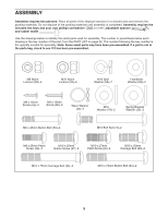
M10 x 75mm Carriage Bolts 34 and two M10 Nylon
 |
View all ProForm 595 Hr manuals
Add to My Manuals
Save this manual to your list of manuals |
Page 6 highlights
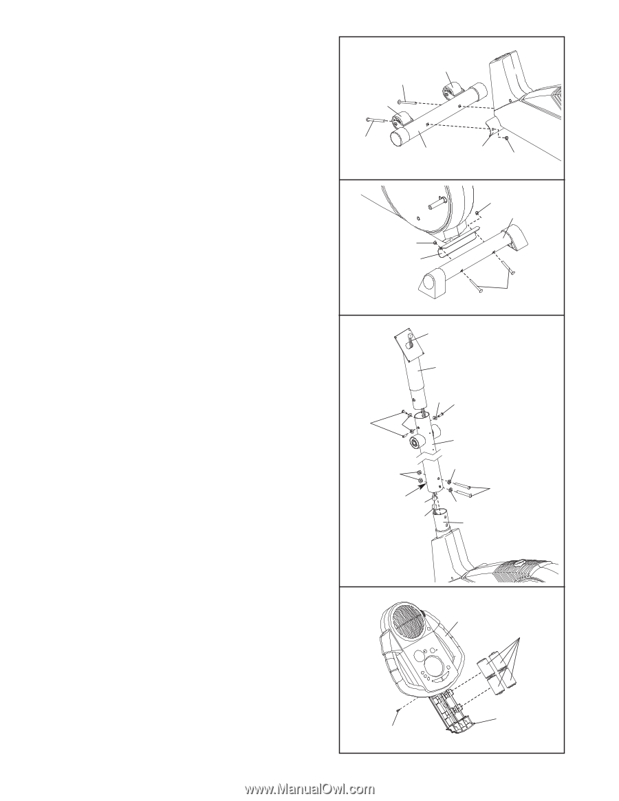
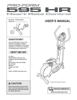
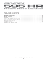
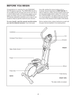
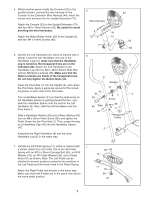
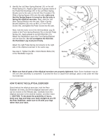
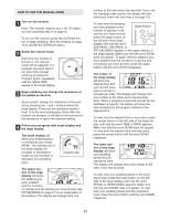
1. Identify the Front Stabiliser (10). Whilst another person lifts the front of the Frame (1), attach the Front 1 Stabiliser to the Frame with two M10 x 75mm Carriage 22 Bolts (34) and two M10 Nylon Locknuts (33). Make 34 sure that the Front Stabiliser is turned so the Wheels (22) are not touching the floor. 22 2. Whilst another person lifts the back of the Frame (1), attach the Rear Stabiliser (9) to the Frame with two M10 x 75mm Carriage Bolts (34) and two M10 Nylon Locknuts (33). 3. Whilst another person holds the Upright (2) in the position shown, connect the Extension Wire Harness (44) to the Wire Harness (79). Carefully pull the upper end of the Extension Wire Harness to remove any slack, and slide the Upright onto the Frame (1). Be careful not to pinch the Wire Harnesses. Attach the Upright with two M10 x 72mm Button Bolts (84), two M10 Split Washers (59), and two M10 Nylon Locknuts (33). Feed the upper end of the Extension Wire Harness (44) through the Upright Extension (73). Whilst holding the upper end of the Extension Wire Harness, insert the Upright Extension into the Upright (2). Be careful not to pinch the Extension Wire Harness. Attach the Upright Extension with three M10 x 25mm Button Screws (67) and three M10 Split Washers (59). Make sure that the Nylon Locknuts are inside of the hexagonal holes. 34 10 1 33 2 33 9 33 1 34 3 44 Make sure the Wire Harnesses (44, 79) do not 73 get pinched and damaged during 59 67 this step. 67 59 2 33 Hexagonal Holes 44 79 59 84 59 1 4. The Console (23) requires four 1.5V "D" batteries; 4 alkaline batteries are recommended. Remove the indi- cated screw from the battery drawer, and pull the bat- tery drawer open. Insert four batteries into the battery drawer; make sure that the batteries are oriented as shown by the markings inside of the battery drawer. Close the battery drawer and reattach the screw. Note: When the batteries are installed correctly, the fan will turn on for a moment. Screw 6 23 Batteries Battery Drawer
-
 1
1 -
 2
2 -
 3
3 -
 4
4 -
 5
5 -
 6
6 -
 7
7 -
 8
8 -
 9
9 -
 10
10 -
 11
11 -
 12
12 -
13
-
14
-
15
-
16
-
17
-
18
-
19
-
20
-
21
-
22
-
23
-
24
 |
 |