ProForm 595 Hr Uk Manual - Page 7
Knob 81 as shown. Note: The Left Pedal can
 |
View all ProForm 595 Hr manuals
Add to My Manuals
Save this manual to your list of manuals |
Page 7 highlights
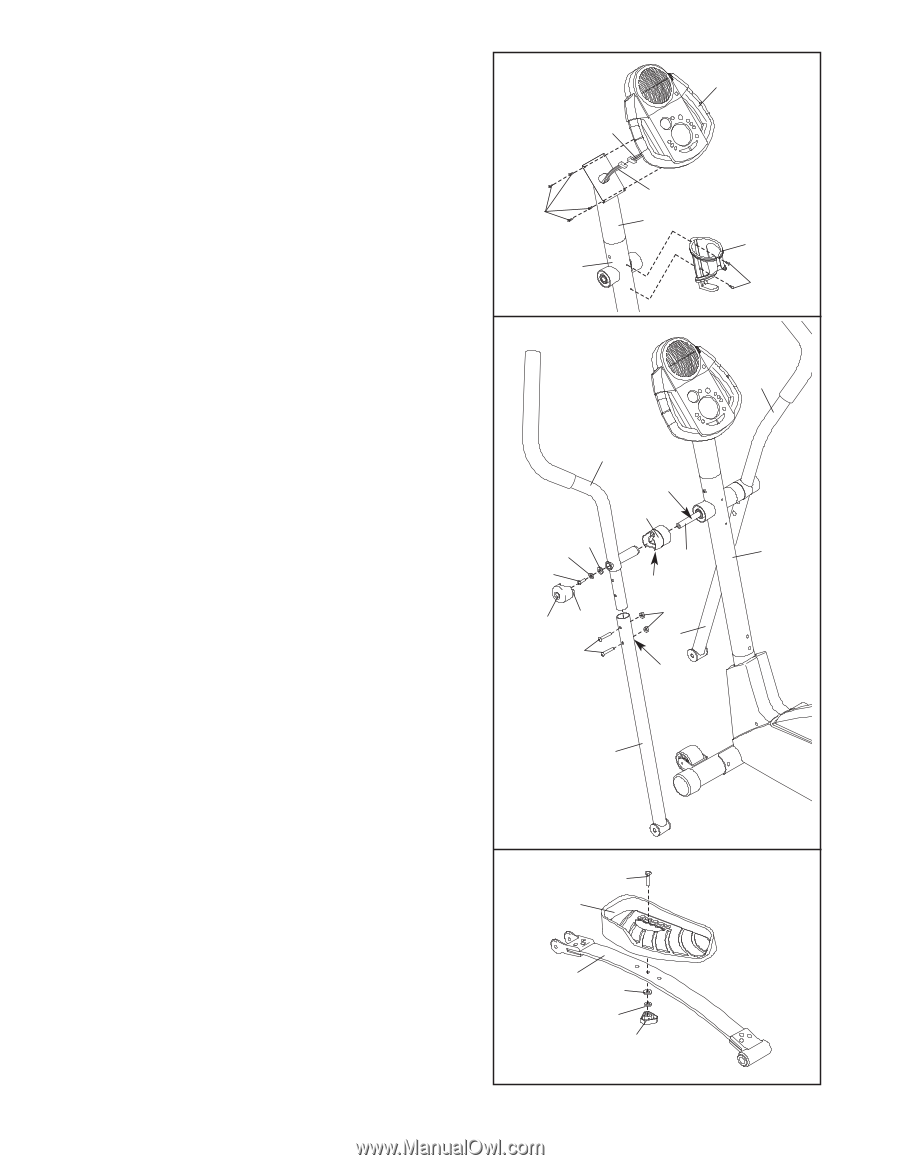
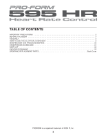
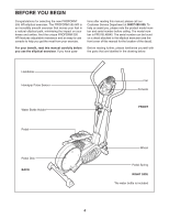
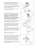
5. Whilst another person holds the Console (23) in the position shown, connect the wire harness on the Console to the Extension Wire Harness (44). Insert the excess wire harness into the Upright Extension (73). Attach the Console (23) to the Upright Extension (73) with four M4 x 16mm Screws (52). Be careful to avoid pinching the wire harnesses. Attach the Water Bottle Holder (65) to the Upright (2) with two M4 x 19mm Screws (86). 6. Identify the Left Handlebar (6), which is marked with a sticker. Insert the Left Handlebar into one of the Handlebar Legs (5); make sure that the Handlebar Leg is turned so the hexagonal holes are on the indicated side. Attach the Left Handlebar to the Handlebar Leg with two M8 x 45mm Button Bolts (50) and two M8 Nylon Locknuts (38). Make sure that the Nylon Locknuts are inside of the hexagonal holes. Do not fully tighten the Button Bolts yet. Insert the Pivot Axle (7) into the Upright (2), and center the Pivot Axle. Apply a generous amount of the included grease to both ends of the Pivot Axle. Turn a Handlebar Spacer (47) so that the small arrow on the Handlebar Spacer is pointing toward the floor, and slide the Handlebar Spacer onto the post on the Left Handlebar (6). Next, slide the Left Handlebar onto the Pivot Axle (7). Slide a Handlebar Washer (55) and a Wave Washer (43) onto an M8 x 25mm Patch Screw (56), and tighten the Patch Screw into the Pivot Axle (7). Then, press the tabs on a Handlebar Cap (46) into the Handlebar Spacer (47). Assemble the Right Handlebar (8) and the other Handlebar Leg (5) in the same way. 5 23 Wire Harness 44 52 73 65 2 86 6 8 6 Grease 47 43 55 7 2 56 Arrow 46 Tabs 50 38 5 Hexagonal Holes 5 7. Identify the left Pedal Spring (11), which is marked with 7 a sticker. Attach the Left Pedal (13) to the left Pedal Spring with an M10 x 30mm Carriage Bolt (80), an M10 Washer (78), an M10 Split Washer (59), and a Pedal Knob (81) as shown. Note: The Left Pedal can be attached in several positions using the five positions in the Left Pedal and the three holes in the Pedal Spring. Attach the Right Pedal (not shown) in the same way. Make sure that both Pedals are in the same hole and in the same pedal position. 80 13 11 78 59 81 7
-
 1
1 -
 2
2 -
 3
3 -
 4
4 -
 5
5 -
 6
6 -
 7
7 -
 8
8 -
 9
9 -
 10
10 -
 11
11 -
 12
12 -
13
-
14
-
15
-
16
-
17
-
18
-
19
-
20
-
21
-
22
-
23
-
24
 |
 |