ProForm 6.0 Gsx Treadmill English Manual - Page 23
PART LIST-Model No. PFTL51105.1
 |
View all ProForm 6.0 Gsx Treadmill manuals
Add to My Manuals
Save this manual to your list of manuals |
Page 23 highlights
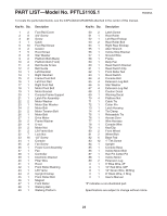
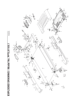
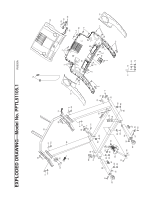
PART LIST-Model No. PFTL51105.1 R0605A To locate the parts listed below, see the EXPLODED DRAWING attached in the center of this manual. Key No. Qty. 12 28 3 41 41 5 10 62 75 88 92 10 2 11 4 12 2 13 1 14 1 15 2 16 1 17 1 18 1 19 1 20 1 21 1 22 2 23 1 24 2 25 2 26 1 27 1 28 2 29 4 30 2 31 2 32 7 33 16 34 1 35 2 36 1 37 1 38 1 39 1 40 1 41 1 42 1 43 1 44 2 45 1 46 1 47 1 48 1 49 1 Description Foot Rail Cover 3/4" Screw Screw Catch Foot Rail Screw Isolator Hood Screw Star Washer Platform Bolt (Back) Platform Bolt (Front) Belt Guide Screw Belt Guide Left Handrail Right Handrail Frame Pivot Bolt Left Foot Rail Right Foot Rail Motor Pivot Bolt Motor Bracket Console Frame Support Latch Pin Assembly Motor Washer Motor Star Washer Motor Bolt Motor Tension Bolt Motor Belt Drive Motor Frame Washer U-nut Motor Nut Lift Frame Bolt Lock Nut 1/2" Screw Console Fan Screw Power Cord Assembly Fan Controller Electronic Bracket Filter Wire Hood Front Roller Bushing Lift Frame Upright Endcap Front Roller Bolt Magnet Front Roller Walking Belt Walking Platform Key No. Qty. 50 2 51 1 52 1 53 2 54 1 55 1 56 1 57 1 58 1 59 1 60 1 61 1 62 1 63 1 64 4 65 4 66 5 67 4 68 2 69 1 70 4 71 1 72 1 73 1 74 4 75 1 76 1 77 1 78 1 79 1 80 2 81 2 82 6 83 12 84 1 85 1 86 1 87 1 88 1 89 2 #1 #1 #1 #1 #1 Description Latch Screw Rear Roller Left Rear Endcap Rear Roller Bolt Right Rear Endcap Allen Wrench Incline Stop Bracket Ground Wire Frame Belly Pan Reed Switch Bracket Reed Switch Clip Front Roller Nut Reed Switch Console Bolt Extension Leg Bolt Star Washer Extension Leg Nut Caution Decal Warning Decal Platform Nut Cable Tie Cotter Pin Latch Housing Tie Clamp Releasable Tie Access Door Wire Harness Console Wire Key/Clip Front Wheel Wheel Bolt Base Pad 1" Tek Screw Upright Console Base Incline Motor Bolt Hair Pin Cotter Pin Incline Motor Extension Leg 6" Blue Wire, 2F 10" Red Wire, M/F 12" Green Wire, M/Ring 8" Black Wire, 2 Ring User's Manual "#" indicates a non-illustrated part. Specifications are subject to change without notice. 23
-
 1
1 -
2
-
3
-
4
-
5
-
6
-
7
-
8
-
9
-
10
-
11
-
12
-
13
-
14
-
15
-
16
-
17
-
 18
18 -
 19
19 -
 20
20 -
 21
21 -
 22
22 -
 23
23 -
 24
24 -
 25
25 -
 26
26
 |
 |
