ProForm 6.0 Gsx Treadmill English Manual - Page 7
Be Damaged When The Power Is Turned On. - 6 treadmill
 |
View all ProForm 6.0 Gsx Treadmill manuals
Add to My Manuals
Save this manual to your list of manuals |
Page 7 highlights
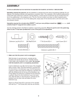
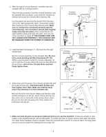
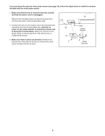
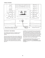
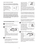
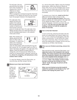
2. With the help of a second person, carefully raise the Uprights (84) to a vertical position. 2 Have the second person hold the console assembly near the Uprights (84) as shown. Look under the console assembly and locate the Console Wire Harness (78). Cut the plastic ties securing the Upright Wire Harness (77) to the right Upright (84). Next, connect the Upright Wire Harness to the Console Wire Harness (78). Make sure to connect the connectors properly (see the inset drawing). The connectors should slide together easily and snap into place. If the connectors do not slide together easily and snap into place, turn one connector and then try again. IF THE CONNECTORS ARE NOT CONNECTED PROPERLY, THE CONSOLE MAY BE DAMAGED WHEN THE POWER IS TURNED ON. Console Assembly 78 77 78 77 84 3. Insert the Wire Harnesses (77, 78) down into the right Upright (84). Set the console assembly on the Uprights (84). Be careful to avoid pinching the Wire Harnesses (77, 78). While a second person holds the console assembly, attach it with four Console Bolts (64) and four Star Washers (8) as shown; start all four Console Bolts and then firmly tighten them. 3 Console Assembly 77, 78 8 64 84 8 64 84 4. Attach the Latch Housing (73) to the left Upright (84) with 4 two Latch Screws (50); start both Latch Screws and then tighten them. Note: Make sure that the large 84 hole in the Housing is on the indicated side. Remove the knob from the pin. Make sure that the collar and the spring are on the pin. (Note: If there are two collars, place one on each side of the spring.) Next, insert the pin into the Latch Housing (73). Then, tighten the knob back onto the pin. Knob 50 73 Spring Large Hole Collar Pin 5. Make sure that all parts are properly tightened before you use the treadmill. If there are sheets of clear plastic on the treadmill decals, remove the plastic. To protect the floor or carpet, place a mat under the treadmill. Note: Extra hardware may be included. Keep the included allen wrench in a secure place; the large allen wrench is used to adjust the walking belt (see page 20). 7
-
 1
1 -
 2
2 -
 3
3 -
 4
4 -
 5
5 -
 6
6 -
 7
7 -
 8
8 -
 9
9 -
 10
10 -
 11
11 -
 12
12 -
13
-
14
-
15
-
16
-
17
-
18
-
19
-
20
-
21
-
22
-
23
-
24
-
25
-
26
 |
 |
