ProForm 630 Weight Bench User Manual - Page 7
the Front Leg 19.
 |
View all ProForm 630 Weight Bench manuals
Add to My Manuals
Save this manual to your list of manuals |
Page 7 highlights
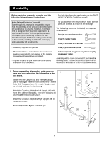
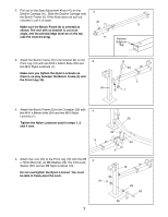
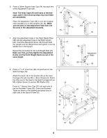
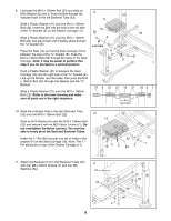
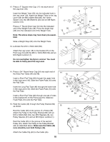
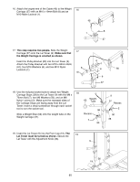
2. Pull out on the Seat Adjustment Knob (47) on the 2 Decline Carriage (11). Slide the Decline Carriage onto the Bench Frame (5). If the Knob does not pull out, unscrew it until it is loose. 47 5 Make sure the Bench Frame (5) is oriented as shown. The end with no bracket is cut at an angle, and the pointed edge must be on the top (see the inset drawing). 11 Pointed Edge on Top 3. Attach the Bench Frame (5) to the bracket (B) on the Front Leg (19) with two M10 x 63mm Bolts (33) and two M10 Nylon Locknuts (1). Make sure you tighten the Nylon Locknuts so there is no play between the Bench Frame (5) and the Front Leg (19). 3 19 33 5 B 1 4. Attach the Bench Frame (5) to the Crossbar (20) with 4 two M10 x 68mm Bolts (34) and two M10 Nylon Locknuts (1). Tighten the Nylon Locknuts used in steps 1, 2 and 4 now. 34 5 5. Attach the Lock (55) to the Front Leg (19) with the M8 x 70mm Bolt (52), an M8 Washer (23), the 7mm Lock Spacer (65), and an M8 Nylon Locknut (13). Do not overtighten the Nylon Locknut. You must be able to freely pivot the Lock. 5 13 1 23 20 34 19 65 52 55 7
-
 1
1 -
 2
2 -
 3
3 -
 4
4 -
 5
5 -
 6
6 -
 7
7 -
 8
8 -
 9
9 -
 10
10 -
 11
11 -
 12
12 -
13
-
14
-
15
-
16
-
17
-
18
-
19
-
20
-
21
-
22
 |
 |
