ProForm 650 English Manual - Page 8
Attach the Weight Guides 23 to the Top Frame
 |
View all ProForm 650 manuals
Add to My Manuals
Save this manual to your list of manuals |
Page 8 highlights
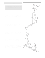
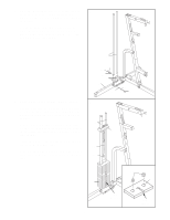
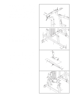
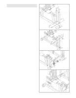
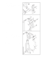
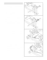
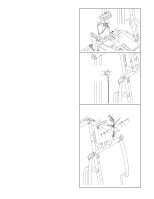
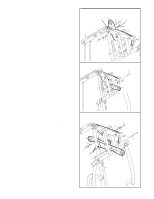
5. Slide the welded tubes on the Top Frame (1) over 5 the upper ends of the Weight Guides (23). Align the bracket on the Top Frame with the indicated holes in the Main Upright (3). Insert two 3/8" x 3" Bolts (45) into the holes. Thread a 3/8" Nylon 50 Locknut (50) onto the lower Bolt. Do not thread a Locknut onto the upper Bolt yet. Attach the Weight Guides (23) to the Top Frame (1) with two 3/8" x 1 3/4" Bolts (60) and two 3/8" Nylon Locknuts (50). Welded Tubes 6. Press a 2" x 3" Inner Cap (24) into the end of the Leg Press Base (84). Slide the Leg Press Base (84) onto the 3/8" x 3 3/4" Carriage Bolt (52) and the 3/8" x 5" Carriage Bolt (82) in the Stabilizer (5). Tighten a 3/8" Nylon Locknut (50) onto the 3/8" x 3 3/4" Carriage Bolt. Do not place a Nylon Locknut on the 3/8" x 5" Carriage Bolt yet. 6 50 82 52 5 Bracket 1 50 60 23 84 45 3 24 7. Turn the Adjustment Knob (9) on the Sliding Seat 7 Frame (74) counterclockwise to loosen it. Pull out the Knob as far as possible and slide the Sliding Seat Frame onto the Seat Frame Channel (88). Release the Knob and let it engage one of the adjustment holes in the Seat Frame Channel. Tighten the Knob fully. Press a 2" Square Inner Cap (33) into the top of the Sliding Seat Frame (74). Press a 2" Square Inner Cap into the indicated end of the Seat Frame Channel (88). Press the Flat Plate (4) and the Angle Cap (99) onto the other end of the Seat Frame Channel. 8 8. Attach the Seat Frame Channel (88) to the Leg Press Base (84) with four 3/8" x 3" Carriage Bolts (64) and four 3/8" Nylon Locknuts (50). Tighten the 3/8" Nylon Locknuts (50) used in steps 1 and 2. 33 9 33 Adjustment Holes 64 74 88 4 99 88 50 50 50 84 64 50 8
-
 1
1 -
2
-
 3
3 -
 4
4 -
 5
5 -
 6
6 -
 7
7 -
 8
8 -
 9
9 -
 10
10 -
 11
11 -
 12
12 -
 13
13 -
14
-
15
-
16
-
17
-
18
-
19
-
20
-
21
-
22
-
23
-
24
-
25
-
26
-
27
-
28
-
29
-
30
-
31
-
32
-
33
 |
 |
