ProForm 760 English Manual - Page 11
Trouble, Shooting, Maintenance
 |
View all ProForm 760 manuals
Add to My Manuals
Save this manual to your list of manuals |
Page 11 highlights
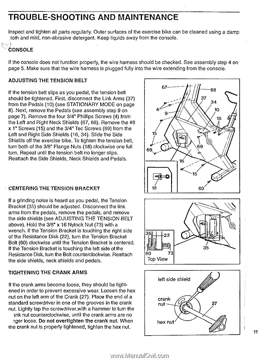
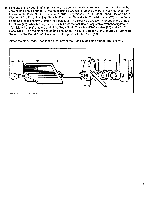
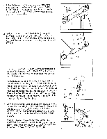
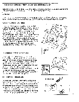
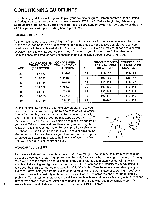
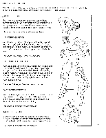
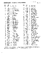
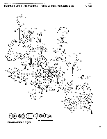
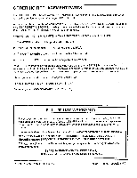
TROUBLE-SHOOTING AND MAINTENANCE Inspect and tighten all parts regularly. Outer surfaces of the exercise bike can be cleaned using a damp :loth and mild, non-abrasive detergent. Keep liquids away from the console. CONSOLE If the console does not function properly, the wire harness should be checked. See assembly step 4 on page 5. Make sure that the wire harness is plugged fully into the wire extending from the console. ADJUSTING THE TENSION BELT If the tension belt slips as you pedal, the tension belt should be tightened. First, disconnect the Link Arms (37) from the Pedals (10) (see STATIONARY MODE on page 8). Next, remove the Pedals (see assembly step 9 on page 7). Remove the four 3/4" Phillips Screws (4) from the Left and Right Neck Shields (67, 68). Remove the #8 x 1" Screws (15) and the 3/4" Tec Screws (69) from the Left and Right Side Shields (16, 34). Slide the Side Shields off the exercise bike. To tighten the tension belt, turn both of the 3/8" Range Nuts (18) clockwise one full turn. Repeat until the tension belt no longer slips. Reattach the Side Shields, Neck Shields and Pedals. 67 4 9 15 16 68 37 34 10 15 69 15 CENTERING THE TENSION BRACKET 18 69 If a grinding noise is heard as you pedal, the Tension Bracket (35) should be adjusted. Disconnect the link arms from the pedals, remove the pedals, and remove the side shields (see ADJUSTING THE TENSION BELT above). Hold the 3/8" x 16 Nylock Nut (73) with a wrench. If the Tension Bracket is touching the right side of the Resistance Disk (22), turn the Tension Bracket 35 22 Bolt (60) clockwise until the Tension Bracket is centered. If the Tension Bracket is touching the left side of the 35 Resistance Disk, turn the Bolt counterclockwise. Reattach 60 73 the side shields, neck shields and pedals. Top View TIGHTENING THE CRANK ARMS If the crank arms become loose, they should be tight- left side shield ened in order to prevent excessive wear. Loosen the hex nut on the left arm of the Crank (27). Place the end of a crank standard screwdriver in one of the grooves in the crank nut 27 nut. Lightly tap the screwdrivermith a hammer to turn the ink nut counterclockwise, until the crank arms are no nger loose. Do not overtlghten the crank nut. When hex nut the crank nut is properly tightened, tighten the hex nut. 11
-
 1
1 -
2
-
3
-
4
-
5
-
 6
6 -
 7
7 -
 8
8 -
 9
9 -
 10
10 -
 11
11 -
 12
12 -
 13
13 -
 14
14 -
 15
15 -
 16
16
 |
 |