ProForm 860 Owners Manual - Page 10
Model
 |
View all ProForm 860 manuals
Add to My Manuals
Save this manual to your list of manuals |
Page 10 highlights
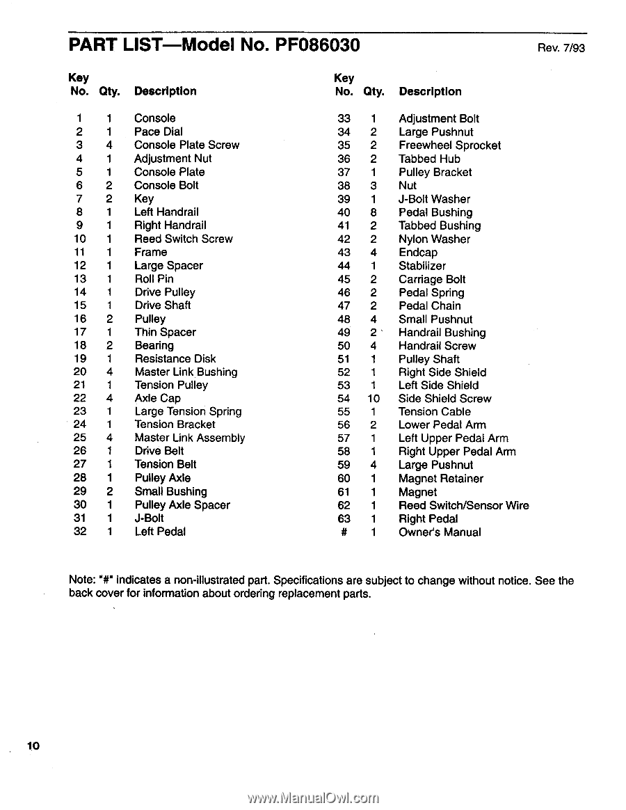
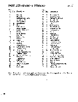
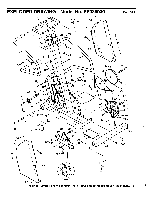
PART LIST Model No. PF086030 Rev. 7/93 Key No. Qty. Description 1 1 Console 2 1 Pace Dial 3 4 Console Plate Screw 4 1 Adjustment Nut 5 1 Console Plate 6 2 Console Bolt 7 2 Key 8 1 Left Handrail 9 1 Right Handrail 10 1 Reed Switch Screw 11 1 Frame 12 1 Large Spacer 13 1 Roll Pin 14 1 Drive Pulley 15 1 Drive Shaft 16 2 Pulley 17 1 Thin Spacer 18 2 Bearing 19 1 Resistance Disk 20 4 Master Link Bushing 21 1 Tension Pulley 22 4 Axle Cap 23 1 Large Tension Spring 24 1 Tension Bracket 25 4 Master Link Assembly 26 1 Drive Belt 27 1 Tension Belt 28 1 Pulley Axle 29 2 Small Bushing 30 1 Pulley Axle Spacer 31 1 J-Bolt 32 1 Left Pedal Key No. Qty. Description 33 1 34 2 35 2 36 2 37 1 38 3 39 1 40 8 41 2 42 2 43 4 44 1 45 2 46 2 47 2 48 4 49 2 50 4 51 1 52 1 53 1 54 10 55 1 56 2 57 1 58 1 59 4 60 1 61 1 62 1 63 1 # 1 Adjustment Bolt Large Pushnut Freewheel Sprocket Tabbed Hub Pulley Bracket Nut J-Bolt Washer Pedal Bushing Tabbed Bushing Nylon Washer Endcap Stabilizer Carriage Bolt Pedal Spring Pedal Chain Small Pushnut Handrail Bushing Handrail Screw Pulley Shaft Right Side Shield Left Side Shield Side Shield Screw Tension Cable Lower Pedal Arm Left Upper Pedal Arm Right Upper Pedal Arm Large Pushnut Magnet Retainer Magnet Reed Switch/Sensor Wire Right Pedal Owner's Manual Note: 'lir indicates a non-illustrated part. Specifications are subject to change without notice. See the back cover for information about ordering replacement parts. 10
-
 1
1 -
2
-
3
-
4
-
 5
5 -
 6
6 -
 7
7 -
 8
8 -
 9
9 -
 10
10 -
 11
11 -
 12
12
 |
 |