ProForm 860 Owners Manual - Page 4
Assembly
 |
View all ProForm 860 manuals
Add to My Manuals
Save this manual to your list of manuals |
Page 4 highlights
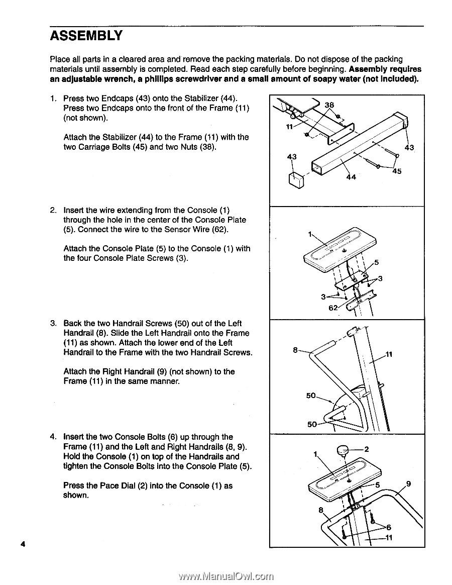
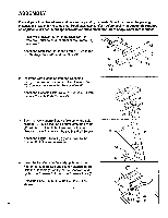
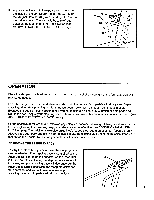
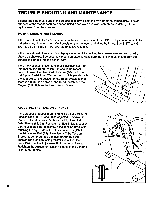
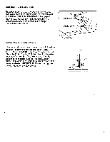
ASSEMBLY Place all parts in a cleared area and remove the packing materials. Do not dispose of the packing materials until assembly is completed. Read each step carefully before beginning. Assembly requires an adjustable wrench, a phillips screwdriver and a small amount of soapy water (not included). 1. Press two Endcaps (43) onto the Stabilizer (44). Press two Endcaps onto the front of the Frame (11) (not shown). Attach the Stabilizer (44) to the Frame (11) with the two Carriage Bolts (45) and two Nuts (38). 38 11 ---. . 43 - . 44 . 43 45 2. Insert the wire extending from the Console (1) through the hole in the center of the Console Plate (5). Connect the wire to the Sensor Wire (62). Attach the Console Plate (5) to the Console (1) with the four Console Plate Screws (3). 3. Back the two Handrail Screws (50) out of the Left Handrail (8). Slide the Left Handrail onto the Frame (11) as shown. Attach the lower end of the Left Handrail to the Frame with the two Handrail Screws. Attach the Right Handrail (9) (not shown) to the Frame (11) in the same manner. 4. Insert the two Console Bolts (6) up through the Frame (11) and the Left and Right Handrails (8, 9). Hold the Console (1) on top of the Handrails and tighten the Console Bolts into the Console Plate (5). Press the Pace Dial (2) into the Console (1) as shown. 4 1 __,.„- , A 5 / e 3 '0 3-- -----24 62 • 8 11 1, 50 50 1 Q2 5 .--%-- 9 / 8 1. ) 6 11
-
 1
1 -
 2
2 -
 3
3 -
 4
4 -
 5
5 -
 6
6 -
 7
7 -
 8
8 -
 9
9 -
 10
10 -
11
-
12
 |
 |