ProForm C600 Bench User Manual - Page 6
Passembly - press
 |
View all ProForm C600 Bench manuals
Add to My Manuals
Save this manual to your list of manuals |
Page 6 highlights
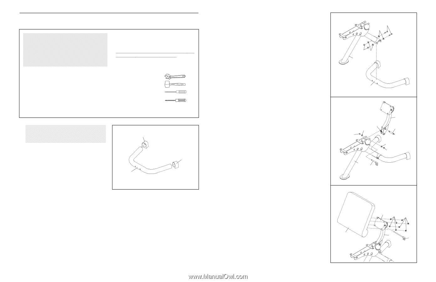
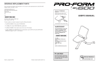
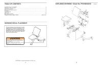
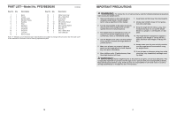
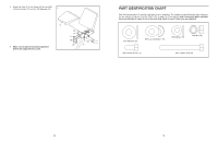
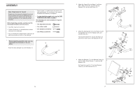
ASSEMBLY Make Things Easier for Yourself Everything in this manual is designed to ensure that the weight bench can be assembled successfully by anyone. Most people find that by setting aside plenty of time, assembly will go smoothly. Before beginning assembly, carefully read the following information and instructions: • Assembly requires two persons. • Tighten all parts as you assemble them, unless instructed to do otherwise. • As you assemble the weight bench, make sure all parts are oriented as shown in the drawings. • Place all parts in a cleared area and remove the packing materials. Do not dispose of the packing materials until assembly is completed. • For help identifying small parts, use the PART IDENTIFICATION CHART on page 5. The following tools (not included) are required for assembly: • Two adjustable wrenches • One rubber mallet • One standard screwdriver • One Phillips screwdriver 1. Before beginning assembly, make sure you 1 understand the information in the box 12 above. Press two Base Endcaps (12) onto the Base (1). 12 1 6 2. Attach the Frame (2) to the Base (1) with two M10 x 80mm Bolts (22), four M10 Curved 2 Washers (19), and two M10 Nuts (21). 22 19 21 19 2 3. Attach the Backrest Arm (3) to the Frame (2) with the Shaft Bolt (9), two M10 Washers (20), and 3 two M10 Nuts (21). Fully insert the Short Pin (10) into the Frame (2) and into the lower tube in the Backrest Arm (3). 1 3 Lower Tube 20 9 21 20 21 2 10 4. Attach the Backrest (7) to the Backrest Frame (4) 4 with four M8 x 20mm Screws (17) and four M8 Washers (18). Full insert the Long Pin (11) into the Backrest Frame (4) and the Backrest Arm (3). 7 4 18 17 3 11 7
-
 1
1 -
 2
2 -
 3
3 -
 4
4 -
 5
5 -
 6
6
 |
 |