ProForm Crosswalk Caliber11 Treadmill English Manual - Page 8
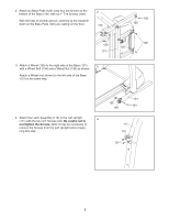
Attach the Left Handrail 108 to the Left Upright 111
 |
View all ProForm Crosswalk Caliber11 Treadmill manuals
Add to My Manuals
Save this manual to your list of manuals |
Page 8 highlights
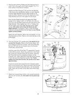
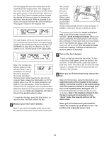
5. See the inset drawing. Make sure that there are two Unuts (112) in the upper end of each Upright (119, 111). Note: Extra U-nuts may be included. Identify the Right Handrail (120) and the Left Handrail (108); there is an identification sticker on each Handrail. Hold the Right Handrail near the Right Upright (119). Insert the Wire Harness (118) into the large hole in the Right Handrail and out of the upper end as shown. Next, hold the Right Handrail (120) against the Right Upright (119). Tighten a 3/8" x 3 1/2" Bolt (121) three to four turns into the Right Upright and the lower end of the Right Handrail. Then, tighten two 5/16" x 1" Bolts (113) into the upper end of the Right Handrail and the Right Upright. Be careful not to drop the Bolts into the Right Handrail. If necessary, raise or lower the Right Handrail to thread the Bolts into the Right Upright. Firmly tighten all three Bolts. Attach the Left Handrail (108) to the Left Upright (111) as described above. Note: There is not a wire harness in the Left Upright. 5 113 108 119 112 118 111 113 121 120 119 121 6. Turn the Console (101) upside-down; be careful not to scratch the Console. Remove the Console Back (104 [see drawing 7]) from the Console. If the four Pulse Bar Screws (76) (only two are shown) are in the Console Frame (80), remove them. Hold the ends of the Pulse Bar (77) against the Console Frame (80) as shown. Route the pulse wire in the Pulse Bar under the Console Frame (80) as shown, and plug the Pulse Wire into the indicated connector on the Console (101). Next, attach the Pulse Bar to the Console Frame with the four Pulse Bar Screws (76). Firmly tighten the Pulse Bar Screws. Be careful not to damage the wires. Route the ground wires away from the indicated plastic post on the Console (101). Attach the ends of the ground wires to the Console Frame (80) with a 1/2" Screw (52). Note: There are no wires on the other side of the Pulse Bar (77). 6 52 Plastic 77 80 Post 76 101 Ground Wires Pulse Wire Connector 7. Attach the Console Back (104) to the console assembly with five 3/4" Screws (33). Be careful not to pinch any wires. 7 33 33 104 33 Console Assembly 8
-
 1
1 -
2
-
 3
3 -
 4
4 -
 5
5 -
 6
6 -
 7
7 -
 8
8 -
 9
9 -
 10
10 -
 11
11 -
 12
12 -
 13
13 -
14
-
15
-
16
-
17
-
18
-
19
-
20
-
21
-
22
-
23
-
24
-
25
-
26
-
27
-
28
-
29
-
30
-
31
-
32
-
33
-
34
 |
 |
