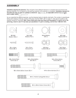
ProForm Xp 115 Elliptical English Manual - Page 6
See step 3. Tighten the M10 x 88mm Button Screws - will not turn on
 |
View all ProForm Xp 115 Elliptical manuals
Add to My Manuals
Save this manual to your list of manuals |
Page 6 highlights
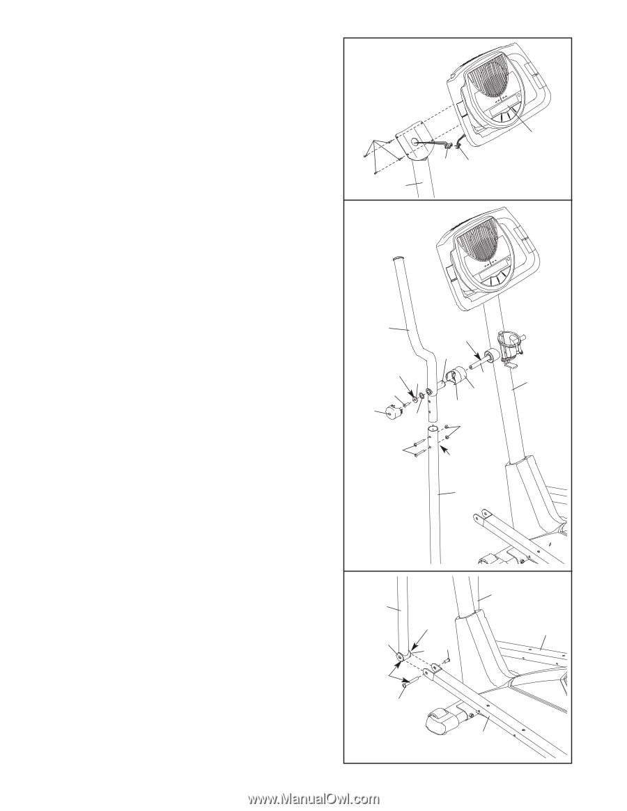
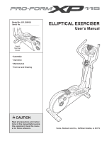
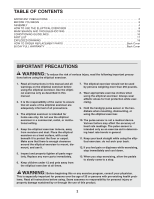
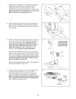
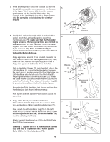
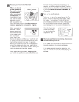
5. While another person holds the Console (5) near the Upright (2), connect the wire harness on the Console to the Upper Wire Harness (86). Insert the excess wire harness into the Upright. Next, attach the Console to the Upright with four M4 x 16mm Screws (66). Be careful to avoid pinching the wire harnesses. 5 66 6. Identify the Left Handlebar (9), which is marked with a sticker. Insert the Left Handlebar into one of the Handlebar Legs (79); make sure that the Handlebar Leg is turned so the hexagonal holes are oriented as indicated. Attach the Left Handlebar to the Handlebar Leg with two M8 x 45mm Button Bolts (50) and two M8 Nylon Locknuts (46). Make sure that the Nylon Locknuts are set inside the hexagonal holes. Do not tighten the Button Bolts yet. Apply a generous amount of the included grease to the Pivot Axle (97) and to two M8 Large Washers (53). Next, insert the Pivot Axle into the Upright (2) and center it. Apply more grease to both ends of the Pivot Axle. Slide a Handlebar Spacer (25) onto the short tube on the Left Handlebar (9), and rotate the Handlebar Spacer so the small arrow is pointing toward the floor. Next, slide the Left Handlebar onto the left end of the Pivot Axle (97). Finger tighten an M8 x 25mm Patch Screw (22) with an M8 Large Washer (53) and a Wave Washer (95) into the end of the Pivot Axle. Then, attach a Handlebar Cap (23) by pressing its small tabs into the Handlebar Spacer. Assemble the Right Handlebar (not shown) and the other Handlebar Leg (not shown) in the same way. 86 Wire Harness 2 6 9 Grease Tube Grease 53 22 23 95 97 25 Arrow 46 50 Hexagonal Holes 79 Now, tighten both M8 x 25mm Patch Screws (22) at the same time. 7. Apply a thin film of grease to the shaft of an M10 x 52mm Bolt Set (27) and to the surfaces of the two Leg Bushings (28) in the left Handlebar Leg (79). Next, attach the left Handlebar Leg (79) to the Left Pedal Arm (14) with the M10 x 52mm Bolt Set (27). Do not overtighten the Bolt Set; the left Handlebar Leg must be able to pivot freely. Attach the right Handlebar Leg (79) to the Right Pedal Arm (103) in the same way. See step 3. Tighten the M10 x 88mm Button Screws (63). See step 6. Tighten the M8 x 45mm Button Bolts (50) in the Handlebar Legs (79). 7 79 79 Grease 28 28 27 Grease 27 14 5 2 103 6
-
 1
1 -
 2
2 -
 3
3 -
 4
4 -
 5
5 -
 6
6 -
 7
7 -
 8
8 -
 9
9 -
 10
10 -
 11
11 -
 12
12 -
13
-
14
-
15
-
16
-
17
-
18
-
19
-
20
 |
 |