ProForm Xp Weight Loss 620 Treadmill User Manual - Page 10
Be Damaged When You Turn On
 |
View all ProForm Xp Weight Loss 620 Treadmill manuals
Add to My Manuals
Save this manual to your list of manuals |
Page 10 highlights
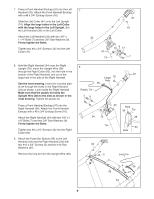
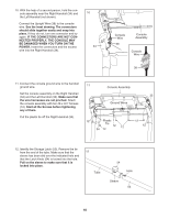
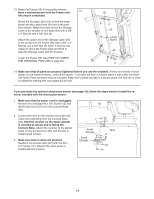
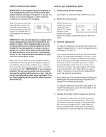
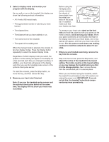
10. With the help of a second person, hold the console assembly near the Right Handrail (34) and the Left Handrail (not shown). Connect the Upright Wire (38) to the console wire. See the inset drawing. The connectors should slide together easily and snap into place. If they do not, turn one connector and try again. IF THE CONNECTORS ARE NOT CONNECTED PROPERLY, THE CONSOLE MAY BE DAMAGED WHEN YOU TURN ON THE POWER. Insert the connectors and the excess wire into the Right Handrail (34). 10 34 Console Wire 38 Console Assembly Console Wire 38 11. Connect the console ground wire to the handrail ground wire. Set the console assembly on the Right Handrail (34) and the Left Handrail (33). Make sure that the wire harnesses are not pinched. Attach the console assembly with ten #8 x 3/4" Screws (12). Start all the Screws before tightening any of them. Cut the plastic tie off the Right Handrail (34). 11 Console Assembly 33 Ground Wires 12 Plastic Tie 12 12 34 12 12 12 12. Identify the Storage Latch (53). Remove the tie from the end of the tube. Make sure that the sleeve has been slid over the indicated hole and that the Latch Knob (54) is locked into the hole. Pull on the sleeve to make sure that it is locked into place. 12 Tube 54 Hole Sleeve 53 10
-
 1
1 -
2
-
3
-
4
-
 5
5 -
 6
6 -
 7
7 -
 8
8 -
 9
9 -
 10
10 -
 11
11 -
 12
12 -
 13
13 -
 14
14 -
 15
15 -
16
-
17
-
18
-
19
-
20
-
21
-
22
-
23
-
24
-
25
-
26
-
27
-
28
-
29
-
30
-
31
-
32
 |
 |
