Pyle HURVBTR63 Instruction Manual - Page 4
Important Notes, Assembly, Instructions For Assembly
 |
View all Pyle HURVBTR63 manuals
Add to My Manuals
Save this manual to your list of manuals |
Page 4 highlights
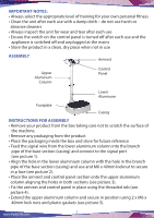
IMPORTANT NOTES: • Always select the appropriate level of training for your own personal fitness • Clean the unit after each use with a damp cloth - do not use harsh or abrasive cleaners • Always inspect the unit for wear and tear after each use • Ensure the switch on the control panel is turned off after each use and the appliance is switched off and unplugged at the mains • Store the product in a clean, dry place when not in use ASSEMBLY Armrest Upper Aluminum Column Control Panel Lower Aluminum Footplate Casing INSTRUCTIONS FOR ASSEMBLY • Remove your product from the box taking care not to scratch the surface of the machine. • Remove any packaging from the product • Place the packaging inside the box and store for future reference • Feed the signal wire from the lower aluminium column into the branch pipe of the base section (casing) and connect to the signal port (see picture 1). • Align the hole in the lower aluminium column with the hole in the branch pipe of the base section (casing) and use and M6 x 40mm locknut to secure in p lace (see picture 2). • Place the armrest and control panel section onto the upper aluminium column aligning the holes in both sections (see picture 3). • Fix the armrest and control panel in place using the threaded rob (see picture 4). • Extend the upper aluminium column and secure in position using 2 x M6 x 40mm lock nuts and plastic gaskets (see picture 5). www.PyleUSA.com 3
-
 1
1 -
 2
2 -
 3
3 -
 4
4 -
 5
5 -
 6
6 -
 7
7 -
 8
8
 |
 |
