Pyle PAD20MXU PAD20MXU Manual 1 - Page 4
Operation, Specifications
 |
View all Pyle PAD20MXU manuals
Add to My Manuals
Save this manual to your list of manuals |
Page 4 highlights
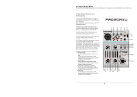
5.2 Operation with power supply unit Via its USB connection, the power supply unit must prov ide an outpu t voltage of 5 V and an output cu rrent of 500m A. Connect the power supply unit to the USB port (5) via t he USB cabl e provided, then connec t it to a mains socket. Switch on the mixer with the switch POWER (8) [position"ON"]. The LED ON / CHA RGE (6) ligh ts up according to the battery ch arge status (chapter 5.3). 5.3 Charging the battery / Battery oper ation To ensure the maximu m operating time (approx . 4 hours) when the mix er is operate d via the integrated rechargeable lithium-ion battery, fully charge th e battery prio r to operatio n. Connect t he USB port (5) to a comp uter (chapte r 5.1) or to a power supply unit (cha pter 5.2). Th e LED ON / CHARGE (6) shows th e charge sta tus and operating mode: 1. With th e mixer switched off [swit ch POWER ( 8) set to"OFF"], the LED ON / CH ARGE show s green while the batt ery is being charged. When the battery has been fully charge d, the LED is extingu ished. 2. With th e mixer switched on [swit ch POWER set to "ON" ], the LED ON / CHAR GE shows red and green (= yellow) at the same time while the battery is being charged. When the battery has be en fully charged, the LED shows red. To save b attery power, the LED ON / CHARGE doesnot light up during battery ope ration. Therefore , you may easily forget to switch off th e mixer. To prevent the b attery from being complete ly discharged, always ma ke sure to se t the switch POWER to "OFF" after operation. 6 Operation 1) Switch on t he mixer with the switch P OWER (8) [position "ON"]. 2) For basic s etting, set th e controls MASTER (14) and GAIN (15) approximately to midposition for the time being. 3) When a mic rophone is c onnected to the jack MIC IN (1), speak into th e microphon e and turn up the corresponding control LE VEL (17) until you ob tain a good microphone s ignal. If you need to turn up the control LEVEL completely for this purpose, further turn up the control GAIN (15). However, if the LE D PK (19) lights up an d is not extin guished imm ediately, turn back th e control GA IN. The LED PK must only briefly light up with level peaks. \4) Use the pa norama control PAN (18) to place the microp hone signal on the stereo base. Adjust the sound with t he controls HI and LO (16). 5) Turn up the control LEV EL (21) for channel CH 2 until you obtain a good input signal. To assign the input signal of the USB port (5) to channel CH 2, press the button US B ASSIGN TO CH 2 (23). When the button is engaged, th e USB input signal and the signal of the input LINE IN (2) u se the same channel. Therefore, do not use th e input LINE IN if you intend to reproduce only the USB inp ut signal Via channel CH 2. Note: When recording via the USB po rt, please pay attention to the risk of feedback if you assign the recording signal of the com puter to channel CH 2 as an inpu t signal. 6) For channe l CH 2, adjus t the sound with the controls HI and LO (20) and the balance with the control BAL (22). 7) Use the controls LEVEL (17, 21) to m ix the input signals of channels CH 1 and C H 2 or to fade them in and out. When a channel is not used, set its control to"0". 8) Use the control MASTE R (14) to set the level of the outp ut signal that is sent via th e jacks MAIN OUT (7), TAPE O UT (4) and th e USB port (5). If o ne of the overload LEDs CLIP (13) shows red, turn back the control MA STER Accordingl y 4 9) The head phone outpu t MONITOR / PHONES (9) allows to monitor the output signal of the mixer. For this pur pose, the but ton TAPE IN ASSIGN TO MONITOR ( 12) must not be engaged. Adjust the headphone volume with the control MONITOR / PHONES (1 0). WARNING! Never adjust the headph ones to a very high volume. Perma nent high vo lumes may damage you r hearing! Yo ur ear will get accustomed to high volu mes which d o not seem to be that high after some time. There fore, do not further increase a high v olume after getting used to it. 10) When a unit is connected to the j acks TAPE IN (3), it is p ossible to monitor the output signal of this unit: 1. If the butt on TAPE IN A SSIGN TO MAIN (11) is engaged: via the outputs MAIN OUT (7), TAPE OUT (4), USB (5) and MONITOR / PHONES (9) . The output signal of th e mixer is also present at these jac ks. Therefore, set the two controls LEVEL (1 7, 21) to "0", if necessar y. 2. If the butt on TAPE IN A SSIGN TO MONITOR (12) is engaged: only via the headphone output MONITOR / PHONES. In this case, it is not possible t o monitor the output sign al of the Mixer via the headpho ne output. 7 Spe cifications Sens itivity/ Imped ance Channel CH 1 MIC IN: 1 mV/ 1.2 kΩ Channel CH 2 LINE IN: 400 m V/ 31 kΩ TAP E IN 100 m V/ 21 kΩ Output level MA IN OUT 5.8 V max. MONITOR / PHONES: . 5 V max. Freq uency range 20 - 20 000 Hz THD 0.1% S / N ratio 89 dB (A weighted ) Tone controls for CH 1 + CH 2 Low frequencies 15 dB / 80 Hz Hig h frequencies: . . . . ±15 d B / 12 kHz Head phone impedance: .≥8Ω USB interface USB 2.0, type B port Phan tom power o f XLR jack MIC IN 18 V Powe r supply 3.7 V rech. Li-ion batte ry or 5 V /500 mA via USB interface Dime nsions 98 *45*135 mm Weig ht 480 g Suita ble operatin g system for U SB operation: . . . . . Wind ows 2000, Wind ows XP, Wind ows Vista, Wind ows 7, Mac OS X Subject to technic al modification. Windows is a registered trademark of Microsoft Corporation in the USA and other countries. Mac OS is a registered trademark of Apple Computer, Inc. in the USA and other countries. 5
-
 1
1 -
 2
2 -
 3
3 -
 4
4
 |
 |