Pyle PAD30MXUBT User Manual - Page 4
≥16ohm.Thus
 |
View all Pyle PAD30MXUBT manuals
Add to My Manuals
Save this manual to your list of manuals |
Page 4 highlights
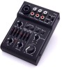
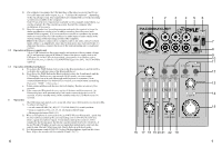
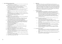
1 Operating Elements and Connections 1. MIC/LINE IN: This combined jack can be used to connect mono signal, such as XLRmicrophone or 1/4" line level. Note: a, Please choose balanced cable and MIC to connect. Do not use the unbalanced ones. When the unit is powered on, remember not to connect the high level signal to XLR Mic In, which may damage the unit. B, At the XLR jack, a phantom power of +18V is always present. 2. Stereo input LINE IN (RCA jacks) to connect an audio source with line signal Level (e.g.CD player) to channel CH2/3. 3. Stereo input 2-TK (RCA jacks) to connect stereo line signal level sources. 4. Stereo outputs MAIN MIX (RCA jacks) to connect the input of an amplifier or a recorder. 5. USB port (type B) to connect a computer or a power supply unit with USB connection; When operating the mixer with a computer, it is possible to use this port as an Audio output (Output of the mixed signal) and as an audio input (feed-in of audio data to be reproduced viaChannel LINE/USB) 6. Power Led: This LED will light up when the unit is powered on. 7. POWER switch 8. HEADSET connections (MIC/PHONES) Note: Headset connected to the built-in microphone, must be connected MIC IN and PHONES in order to avoid unnecessary noise. 9. From LINE IN/ USB Play source selector switch.: Pushing the button in, the signal of channelLlNE/USB comes from USB PLAY(computer); When the Switch is disengaged, signal will be from RCA jacks of channel 2/3. 10. To L1NE/USB switch assigns signal to Main Mix or Monitor(Phones) 11. 2TK/BT control switch: This is the assign control of 2TK input and Bluetooth input. When this control is engaged, the signal of 2TK/BT will be assigned to MONITOR(8). When the controlls disengaged, the signal of 2TK/BT will be Assigned to MAIN MIX (4) and USB (5). 12. Bluetooth PAIR and LED display 13. Volume control MONITOR/PHONES for the headphone output MONITOR/PHONES (8). 14. Overload LEDs CLIP for the stereo output signal adjusted with the control MAIIN MIX (15). 15. MAIN MIX control to set the level of the output signal sent via the outputs MAIN MIX (4) and the USB port (5). 16. Control GAIN for channel CH1 to set the input amplification. 17. High frequency control Hl and low frequency control LO for channel Chl. 18. Control LEVEL for channel Chl. 19. PAN/BAL This is the panorama control or balanced control. This control is used for stereo Effect field of the signal. Set this control in middle position, signal level of Channel L & R will be same. When the control is set to top stop, only Channel L receives the signal, Channel R can not.Vice Versa. 20. PEAK LED This is clip LED indicator of CH1 level. When this LED illuminates, it means that PFL CHI level is clipped. 21. High frequency control HI and low frequency control LO for channel LINE/USB. 22. Control LEVEL for channel LINE / USB 2 2. Applications This compact 3-channel audio mixer with USB interface is suited for universal applications, e.g. For audio recording on the computer. The mono input channel allows to connect a (phantom-powered) microphone; The stereo input channel allows to connect an audio source with line signal level. In addition, the mixer is provided with connections for a recorder and headphones. The mixed signal is sent to the output via a RCA jacks and the USB port. It is also possible to use the USB port as an input to transfer audio data from the computer to the mixer. When connecting the mixer to a computer, power is supplied via the USB connection. When operating the mixer without a computer, either use a suitable power supply unit with USB connection to operate the mixer 3. Setting into Operation Prior to connection/disconnection and prior to each switching on, the output controls MONITOR/PHONES (13) and MAIN MIX (15) should be turned back to ? min? . 1) As audio sources, microphones and/or audio sources with line signal level (e.g. Effect units,musical instruments, players) can be connected to the five input channels.Mono channels Chl :Combined XLR/6.35mm jack are available as inputs (1)-Connect microphones to the balanced XLR jack or HEADSET jacks The XLR jack (CH1) and 3.5mm jack (HEADSET MIC IN) always supplies a +18Vphantom power and it thus suitable for a condenser Microphone operated with this phantom power. Caution! Do not connect a microphone with unbalanced output via XLR plug; it may be damaged by the phantom power. -Connect mono sources with line level to the 6.35 jack. -Do not use both CHI Input (1)-MIC IN and HEADSET (8)-MIC IN. 2) The input LINE IN(2) of the stereo channel LINE/USB allows to connect an audio source with line signal level (e.g. CD player) via RCA plugs: L= left channel, R= right channel. 3) The input 2TK(3) of the stereo channel allows to connect an audio source with line signal level(e.g. Recorder, MP3 player...e.t.c) 4) The 3.5mm jack MONITOR/PHONES(8) allows to connect stereo headphones (Impedance ≥16ohm).Thus, you will be able to monitor the output signal or the input signal of the jacks 2TK(3)via headphones. 5) At the stereo MAIN MIX(4), the output signal adjusted with the MAIN MIX Control(15)is Present. This output allows to connect an amplifier or a second mixer Via a 3.5mm plug 3.1 Operation with a computer When operating the mixer with a computer, either use the audio software supplied with the operating system or an audio software installed additionally. Various programs for audio reproduction/ recording are available on the internet free of charge. 1) Start the computer. Connect the USB port (5) to a USB connection on the computer via the USB cable provided. Switch on the mixer with the switch POWER(7) [Position ON]. The LED ON(6) lights up. 3
-
 1
1 -
 2
2 -
 3
3 -
 4
4
 |
 |
