Pyle PLD7MU PLD7MU Manual 1 - Page 44
Instructions, Wiring Diagram
 |
View all Pyle PLD7MU manuals
Add to My Manuals
Save this manual to your list of manuals |
Page 44 highlights
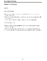
INSTRUCTIONS WIRING DIAGRAM This player is equipped with ISO standard connector, please follow below instruction: • Red - ACC ON (+12V) • Grey/Grey black - Right front speaker (+/-) • Yellow-12 VConstant • White/White black - Left front speaker (+-) • Black - Ground wire • Purple/Purpleblack - Right rear speaker(+/-) • Blue- Power Antenna / RemoteAmpTurn On • Green/Greenblack - Left rear speaker(+/-) • Orange - Back-Up Camera Trigger (+) • Fmk - Parking Brake (-) NGTE:Bssun th• trot is=and la • 12t• Wary•rtt.)1 frard.lbi =WadSPEASER4..:=1Is=end wel.. FEAMEl. sistO•fitttlni Indira* iaart=tar Om! CM Caallimsymbell•lei ISII•g"*. ctoNE • MI 0 IN "Ss M ITimbetslitnrie- g tot to 4, r 4=84Se/efa • • DIN OUP Jul 4 ° ®0 A Eery wit ?Om• : Vdr zym Yam wA3M bto• et! AMmitato, tidAphlhobt•1.) B (ivy WErefuters• inxe sato cete('.1rt.-4110stle) rid lenmaidst . Bata&:Ont(ndObt•IttLrJ Maw wit year14 bra •P-ott.1 Mire Tall• AIR v1401=01 44
-
 1
1 -
2
-
3
-
4
-
5
-
6
-
7
-
8
-
9
-
10
-
11
-
12
-
13
-
14
-
15
-
16
-
17
-
18
-
19
-
20
-
21
-
22
-
23
-
24
-
25
-
26
-
27
-
28
-
29
-
30
-
31
-
32
-
33
-
34
-
35
-
36
-
37
-
38
-
 39
39 -
 40
40 -
 41
41 -
 42
42 -
 43
43 -
 44
44 -
 45
45 -
 46
46
 |
 |
