Pyle PLMCWD25 Instruction Manual - Page 6
BACKUP BATTERY optional, BATTERY MONITOR, ALARM MODULE WIRING, Pin Main harness
 |
View all Pyle PLMCWD25 manuals
Add to My Manuals
Save this manual to your list of manuals |
Page 6 highlights
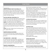
FUNCTIONS sensitivity (level 8=most sensitive), which can be adjusted using the remote transmitter. To adjust the system's built-in shock sensor: 1. Make sure the system is disarmed and ignition is turned off. 2. Press and hold unlock and lighting bolt buttons together to enter adjust mode. t The LCD remote will display a number between 1 and 8 to indicate the sensitivity level, factory setting is level 5; Level 1, least sensitive and level 8, most sensitive. 3. Press lighting bolt button to change sensitivity level. t The siren will chirp a number of times to indicate the sensitivity level, example level 3 chirps and #3 displayed on LCD remote. 4. When desired sensitivity is reached, press unlock button to confirm and exit the setting mode. BACKUP BATTERY (optional) A backup battery provides power to the alarm system when the primary source of power is not available. BATTERY MONITOR When the lock button is press, LCD transmitter will display the motorcycle's battery voltage with a flashing V icon. This will let you know the current battery voltage of the motorcycle. relay. Connect to the motorcycle turn signal wires. If the motorcycle's turn signal circuit exceeds 10 Amps a relay is required. NOTE: Do not connect the YELLOW wire's to the Motorcycle's headlight circuit. t Orange WIRE - +12V Ignition input. Connect to a main ignition wire at the ignition switch harness. This wire shows +12V when the ignition is on and while cranking. The voltage must not drop when the motorcycle is starting. t BLACK WIRES - Ground input (-) connect directly to the Motorcycle's battery or to a solid chassis ground that is clean and free of paint or dirt. t RED WIRE -Main power input (+). Using the supplied inline fuse holder, connect directly to the Motorcycle's battery or alternate power source. t PINK WIRE - Not used. t GREY WIRE -Optional ignition defeat output (-300mA); requires relay (see page 8) . t BLUE WIRE (PLMCWD25/75)- Remote start output. Connect to starter activation wire. 2-Pin LED Connector: Mount LED in an area where it may be easily seen from either side of the Motorcycle. Connect the 2-wire connector to the LED plug. 2-Pin Siren Connector: Mount Siren in an area that is not accessible from potential would be thieves. Connect the 2-wire connector to siren plug. ALARM MODULE WIRING 8-Pin Main harness Yellow WIRE'S - Flashing Light output (+12v) 10A 6
-
 1
1 -
 2
2 -
 3
3 -
 4
4 -
 5
5 -
 6
6 -
 7
7 -
 8
8 -
 9
9 -
 10
10 -
 11
11 -
 12
12
 |
 |
