Pyle PLMCWD75 Instruction Manual - Page 7
ECU installation, ECU light installation, Siren installation
 |
View all Pyle PLMCWD75 manuals
Add to My Manuals
Save this manual to your list of manuals |
Page 7 highlights
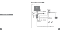
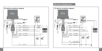
Fuse DC ignition installation diagram Flameout wire 09 ECU installation Please mount the ECU downside as shown in the figure. ECU light installation Siren installation Please mount the siren downwards as shown in the figures 1 or 2 below 1 2 3 1. Drill a hole ( 8) around the block where it can be seen clearly. 2. Insert the outer bushing to the hole. 3. insert the inner bushing with LED to the outer bushing and tighten them up. 4. Connect the LED plug to the main unit of the alarm system. 10
-
 1
1 -
 2
2 -
 3
3 -
 4
4 -
 5
5 -
 6
6 -
 7
7 -
 8
8
 |
 |

09
10
ECU installation
ECU light installation
Siren installation
DC ignition installation diagram
Flameout wire
Please mount the
ECU downside as
shown in the figure.
1. Drill a hole (
8) around the block where it can
be seen clearly.
2. Insert the outer bushing to the hole.
3. insert the inner bushing with LED to the outer
bushing and tighten them up.
4. Connect the LED plug to the main unit of the
alarm system.
Please mount the siren downwards as shown in
the figures 1 or 2 below
1
2
3
Fuse