Pyle PPCX2 PPCX2 Manual 1 - Page 6
Connection Cables, Connection
 |
View all Pyle PPCX2 manuals
Add to My Manuals
Save this manual to your list of manuals |
Page 6 highlights
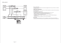
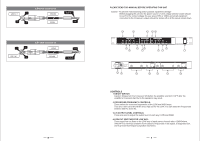
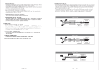
5 PHASE SWITCHES: These allow switching the polarity to invert the signal phase on the HIGH ways. This is done afterthe output levels are set to correct audible phase problems. Caution: Before pressing the PHASE switches, always lower the outputs of your power amplifiers to avoid possible speaker damage. 6 SUB CROSSOVER FREQUENCY CONTROL: This selects the crossover frequency of the SUB WOOFER way. You can select the frequency between 50 Hz to 250 Hz. 7 SUBWOOFER OUTPUT LEVEL CONTROL: This is used to adjust the SUB WOOFER output level. 8 SUBWOOFER LOW CUT SWITCHE: This inserts a low cut filter in the SUBWOOFER way with a 12dB/Octave, 30 Hz HPF to minimize problems from subsonic frequencies in the signal, to suppress hum, and to prevent low frequency subwoofer speaker resonance. CONNECTION 9 FUSE HOLDER / VOLTAGE SELECTOR Your unit may have the AC Voltage Selector (~115V/60Hz or ~230V/50Hz) built into the Fuse Holder. With a small screw driver pull/pop out the Fuse Holder and rotate it so that the arrow showing the proper voltage in your area points toward the other arrow in the upper left comer of plug assembly, and re-insert. 10 STEREO INPUT CONNECTORS: Connect your L/R stereo input signal to either the balanced XLR or the unbalanced 1/4" input jacks. 11 OUTPUT CONNECTORS: Connect to your amplifiers via these unbalanced 1/4" output jacks. 12 Use the enclosed power cord to connect the unit to the mains. 2 CONNECTION CABLES In this chapter you'll find the wiring diagrams for the connectors to be used with your crossover. Take care of the connector cables, always holding them by the connectors and avoiding knots and twists when coiling them: this gives the advantage of increasing their life and reliability, which is always to your advantage. Periodically check that your cables are in good condition, that they are correctly wired and that all their contacts are perfectly efficients: a great number of problems (faulty contacts, ground hum. discharges, etc.) are caused entirely by using unsuitable or faulty cables. 1 3 2 Balanced XLR-M COLD (-) GROUND HOT (+) 2 3 1 Balanced XLR-F COLD (-) HOT (+) GROUND TIP RING Balanced JACK SLEEVE GROUND COLD (-) HOT (+) 3
-
 1
1 -
 2
2 -
 3
3 -
 4
4 -
 5
5 -
 6
6
 |
 |
