Pyle SLFTRD18 Instruction Manual - Page 7
EXPLODED VIEW, Step 2, Step 3
 |
View all Pyle SLFTRD18 manuals
Add to My Manuals
Save this manual to your list of manuals |
Page 7 highlights
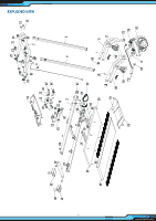
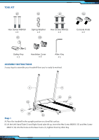
EXPLODED VIEW 59 55 5 17 Main Control Cable Socket 3 4 Step 2 A. Remove the four Head Hex Socket Screws (17) in the end of the Left Stand Tube (3) and Right StandTube(4). B. Attach the Handlebar (5) onto both ends of the Stand Tube (3 and 4), tighten the screws with the Allen Key provided. C. Connect the wire that comes from the Computer Console (55) to the Main Control Cable Socket from the right handlebar support of the Right Stand Tube (4). D. Install both Handlebar Covers (59) onto the Handlebar (5). 55 6 54 Step 3 A. Turn the Computer Console (55) up or down to align the computer knob hole, and then place the Tablet Holder (6) onto the Computer Console (55) to align the hole. B. Lock the Computer Console (55) in place by tightening the Computer Knob (54). 6 www.PyleUSA.com
-
 1
1 -
 2
2 -
 3
3 -
 4
4 -
 5
5 -
 6
6 -
 7
7 -
 8
8 -
 9
9 -
 10
10 -
 11
11 -
 12
12 -
13
-
14
-
15
-
16
-
17
-
18
 |
 |
