RCA DRC8060N User Guide - Page 16
DVD recorder + TV + Basic Cable Box + Audio Receiver
 |
UPC - 034909420201
View all RCA DRC8060N manuals
Add to My Manuals
Save this manual to your list of manuals |
Page 16 highlights
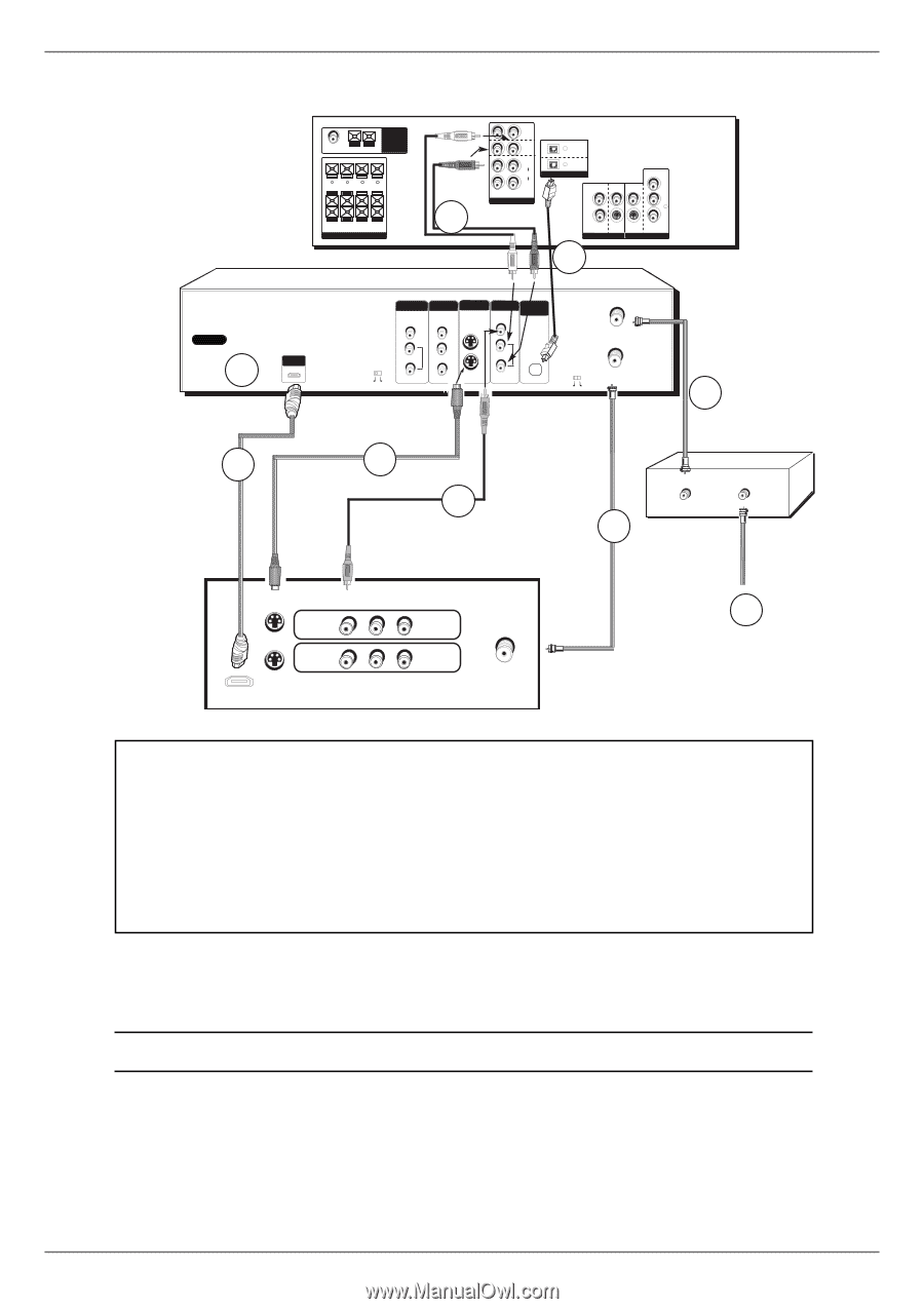
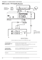
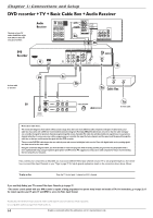
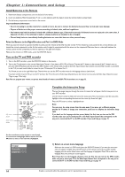
Chapter 1: Connections and Setup DVD recorder + TV + Basic Cable Box + Audio Receiver The back of your TV and/or Cable Box might look different than the ones pictured here. Audio Receiver FM 75Ω GND AM ANTENNA CENTER SUBWOOFER (12Ω) + - - + R - FRONT - L R - REAR - L SPEAKERS (6Ω) 3a TV IN DVD IN IN VCR 1 OUT R L AUDIO DIGITAL AUDIO IN Pr VCR 1 SAT IN IN Pb OUT Y S-VIDEO S-VIDEO (ONLY DVD) VIDEO OUT TO TV / MONITOR 3b DVD Recorder AC IN 4 HDMI OUT INPUT COMPONENT VIDEO OUT S-VIDEO OUTPUT DIGITAL AUDIO OUT VIDEO Y L Pb AUDIO PROG. SCAN R Pr OFF ON VIDEO IN L AUDIO OUT R OPTICAL INPUT CABLE/ANTENNA CH3 CH4 OUTPUT 1b 2e 2c 2b In from cable or antenna CABLE OUT CABLE IN 2a Cable Box TV S-VIDEO VIDEO L R S-VIDEO INPUT1 INPUT2 HDMI/DVI INPUT Use menu for DVI audio. CABLE/ANTENNA 1a In from cable Notes about cable boxes: The connection diagram shown above reflects a basic setup. Since there are many different cable companies and types of cables boxes, your cable box may come with a different recommended connection diagram. Normally, ANALOG cable boxes are used so that the cable company can scramble the signal for premium channel programming (like movie channels).The cable box will descramble the signal if you are a premium channel subscriber. In some cases, your cable company may not scramble the signal for basic channels and the signal could be passed through the cable box so that you could receive the signal with the DVD recorder. There are also DIGITAL cable boxes that are relatively new and are used with digital cable service. Even with digital cable service, analog signals are often carried on the same cable. Using the connection diagram above, you won't be able to watch one program while recording another program.This may be possible with a more sophisticated setup, using an optional signal splitter and A-B switch.We suggest you contact your cable company for help in recommending the best setup for your situation. If you connect your components as described, you must access different Video Input Channels on your TV to see programming. If you don't know how to access Video Input Channels on your TV, go to page 19 for help.A general explanation, based on the connection shown above, follows: To play a disc: Tune the TV to its Input 1 channel or Vid 1 channel. If you need help finding your TV's various Video Input Channels, go to page 19. * The remote control packed with your DVD recorder is capable of being programmed to operate many brands and models of TVs. For instructions, go to page 22. If the remote operates your TV, press TV and INPUT to access the Video Input Channel. Manufactured under license from Dolby Laboratories."Dolby" and the double-D symbol are trademarks of Dolby Laboratories. DTS is a registered trademark of Digital Home Theater Systems, Inc. 14 Graphics contained within this publication are for representation only.
-
 1
1 -
2
-
3
-
4
-
5
-
6
-
7
-
8
-
9
-
10
-
 11
11 -
 12
12 -
 13
13 -
 14
14 -
 15
15 -
 16
16 -
 17
17 -
 18
18 -
 19
19 -
 20
20 -
 21
21 -
22
-
23
-
24
-
25
-
26
-
27
-
28
-
29
-
30
-
31
-
32
-
33
-
34
-
35
-
36
-
37
-
38
-
39
-
40
-
41
-
42
-
43
-
44
-
45
-
46
-
47
-
48
-
49
-
50
-
51
-
52
-
53
-
54
-
55
-
56
-
57
-
58
-
59
-
60
-
61
-
62
-
63
-
64
-
65
-
66
-
67
-
68
 |
 |