Radio Shack 15-1245 Owner's Manual - Page 3
Synchronizing and Testing, Preparing the Antenna Mast, Mounting the Drive Motor, Mounting - controller
 |
UPC - 040293636807
View all Radio Shack 15-1245 manuals
Add to My Manuals
Save this manual to your list of manuals |
Page 3 highlights
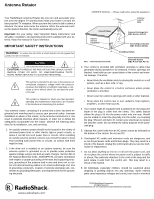
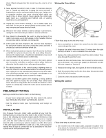
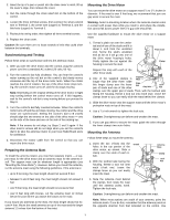
2. Insert the tip of a pen or pencil into the clear cover's notch, lift up the cover's edge, then remove the cover. 3. Run the cable through the strain relief slot on the bottom of the control. 4. Loosen the three terminal screws, then connect the silver-colored wire to Terminal 1, the center wire (copper) to Terminal 2, and the third wire (copper) to Terminal 3. 5. Recheck the wiring order, then tighten all three terminal screws. 6. Replace the clear cover. Caution: Be sure there are no loose strands of wire that could short between the terminals. Synchronizing and Testing Follow these steps to synchronize and test the antenna rotator. 1. After you wire the drive motor and the control, plug the control's power cord into a standard AC outlet (120 volts, 60 Hz). 2. Turn the control's dial fully clockwise. You can hear the control's motor running as the red dot on the control's dial slowly moves clockwise and the top of the drive motor turns. When the rotator reaches the end of rotation, the top of the drive motor stops turning, the control's motor turns off, and the dot stops moving. Note: Depending on the original setting of the drive motor, it might stop turning before the control motor turns off. If this happens, wait for the control's red dot to stop moving before you proceed to Step 3. 3. Turn the control's dial fully counterclockwise. When the control's motor turns off and the dot stops moving, the control and the drive motor are synchronized. Setting the control's dial to N (north) should align the two arrows on the side of the drive motor - one on the side of the base and one on the side of the rotating top. Note: If the arrows do not align, try Steps 2 and 3 again. If the drive motor's arrows still do not align when you set the control's dial to N, take the antenna rotator to your local RadioShack store for assistance. 4. Disconnect the rotator cable from the control so that you can mount the drive motor. Preparing the Antenna Mast To install the antenna rotator, you need two separate masts - a support mast for the drive motor and an antenna mast for the antenna itself. The support mast can be whatever length is appropriate (see "Mounting the Drive Motor"). However, before you mount the antenna, cut the antenna mast using the following guidelines. If the antenna is: • up to 5 feet long, the mast length should not exceed 5 feet • between 5 and 8 feet long, the mast length should not exceed 3 feet • over 8 feet long, the mast length should not exceed 2 feet • over 8 feet long with braces, cut the antenna mast 12 inches below the point where you attach the braces to the mast If you mount two antennas to the mast, the mast length should not exceed 4 feet. Mount the small antenna on top of the mast and the larger antenna 12 inches from the bottom of the mast. Mounting the Drive Motor You can mount the drive motor on a support mast 11/8 to 13/4 inches in diameter. If the mast is over 5 feet long, we recommend that you use guy wires to secure the mast. Warning: Select a mounting location where the antenna cannot come in contact with power lines while you install it, and where the installation cannot fall across power lines if a guy wire should fail. Use the supplied hardware to mount the drive motor on a support mast. 1. Thread a plain nut over the unslotted end of one of the studs until it is about 1 inch from the unslotted end. Screw the stud's unslotted end as far as it will go into one of the drive motor housing's holes. Firmly tighten the nut against the housing to secure the stud. Protrusion Clamp Repeat this step with each of the Stud other three studs. 2. One of the supplied clamps is Support Mast longer than the other three. Slide this longer clamp over the lower pair of studs and one of the other Plain Nut Guy Wire Lock Nut clamps over the upper pair of studs. Then, with the toothed side facing the housing, thread a lock nut onto each stud. Leave the clamps loose so you can easily slide the mast behind the clamps. 3. Slide the drive motor onto the support mast until the drive motor's protrusion rests on top of the mast. 4. Use a 7/16-inch wrench to tighten the lock nuts. Caution: Overtightening can deform and weaken the mast. 5. If you use guy wires to secure the mast, guide the wires through the lower clamp's two outer holes. Mounting the Antenna Follow these steps to mount the antenna. 1. Insert the two U-bolts into the holes in the top portion of the drive motor, as shown. Slide a clamp over the ends of each Ubolt. U-Bolt 2. With the toothed side facing the housing, thread a lock nut onto each U-bolt end. Leave the clamps loose so you can easily insert the mast. Antenna Mast Clamp Lock Nut 3. Slide the antenna mast behind the clamps, then rotate the mast until the antenna points north. Tighten the lock nuts. Caution: Overtightening can deform and weaken the mast. Note: When most stations are south of your antenna, point the antenna south. If you do this, remember that the antenna points in the opposite direction from that indicated on the control. Use 3
-
 1
1 -
 2
2 -
 3
3 -
 4
4
 |
 |