Reebok T 9.80 Treadmill English Manual - Page 9
Bar 99. Hold the Left Handrail 94 near
 |
View all Reebok T 9.80 Treadmill manuals
Add to My Manuals
Save this manual to your list of manuals |
Page 9 highlights
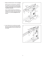
6. Set the console assembly face down on a soft surface to avoid scratching the console assembly. Identify the Right Handrail (102), which is marked with a sticker. Hold the Right Handrail near the console assembly. Next, insert the console wire into the large hole directly below the indicated hole in the Right Handrail (102) and out of the top as shown. 6 Console Assembly Console Wire Hole 102 7. Locate the speed wire in the end of the Pulse Bar (99). Connect the speed wire in the Right 7 Handrail (102) to the speed wire in the Pulse Bar. See the inset drawing. The connectors should slide together easily and snap into place. If they do not, turn one connector and try again. Incline Wires Speed Wires 99 94 Locate the incline wire in the end of the Pulse Bar (99). Hold the Left Handrail (94) near the console assembly. Connect the incline wire in the Left Handrail to the incline wire in the Pulse Bar as described above. 102 Console Assembly 8. Insert the speed wires and incline wires into the area at the end of the Pulse Bar (99). Connect the Left Handrail (94) to the console assembly with two #8 x 1/2" Screws (2), a 3/8" x 3/4" Bolt (10), and a 3/8" Star Washer (11). Make sure no wires are pinched. Attach the Right Handrail (102) to the console assembly in the same way. 8 102 94 11 99 10 2 10 11 2 Console Assembly 9
-
 1
1 -
2
-
3
-
 4
4 -
 5
5 -
 6
6 -
 7
7 -
 8
8 -
 9
9 -
 10
10 -
 11
11 -
 12
12 -
 13
13 -
 14
14 -
15
-
16
-
17
-
18
-
19
-
20
-
21
-
22
-
23
-
24
-
25
-
26
-
27
-
28
-
29
-
30
-
31
-
32
-
33
-
34
-
35
-
36
 |
 |
