Reebok T9.85es Elliptical English Manual - Page 12
Attach the Left Handrail 4 and the Left Rail
 |
View all Reebok T9.85es Elliptical manuals
Add to My Manuals
Save this manual to your list of manuals |
Page 12 highlights
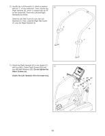
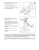
14. Attach the Right Handrail (5) to the Frame (1) with three M10 x 19mm Patch Screws (61) and three M10 Split Washers (79). Press the posts on the Right Rail Cover (7) into the indicated holes in the Frame (1). Attach the Left Handrail (4) and the Left Rail Cover (6) in the same way. 14 4 6 5 7 61 61 79 79 1 Holes 15. Identify the Right Handlebar (11), which is marked with an "R" sticker. Orient the Right 15 Handlebar as shown. Attach the Right Handlebar (11) to the Upright (2) with three M8 x 25mm Flat Patch Screws (68). Then, slide a Handlebar Cover (31) onto the Right Handlebar and attach it with three M4 x 16mm Screws (67). Attach the Left Handlebar (not shown) in the same way. See step 2. Tighten the M10 x 19mm Patch Screws (61). See step 13. Tighten the M8 x 13mm Patch Screws (62). 11 2 68 67 68 31 16. Plug the power adapter into the jack on the frame of the elliptical exerciser (see HOW TO PLUG IN THE POWER SUPPLY on page 13). IMPORTANT: If the elliptical exerciser has been exposed to cold temperatures, allow it to warm to room temperature before plugging in the power cord. If you do not do this, the console displays or other electronic components may become damaged. Make sure that all parts are properly tightened before you use the elliptical exerciser. Note: After assembly is completed, some extra parts may be left over. Place a mat beneath the elliptical exerciser to protect the floor. 12
-
 1
1 -
2
-
3
-
4
-
5
-
6
-
 7
7 -
 8
8 -
 9
9 -
 10
10 -
 11
11 -
 12
12 -
 13
13 -
 14
14 -
 15
15 -
 16
16 -
 17
17 -
18
-
19
-
20
-
21
-
22
-
23
-
24
-
25
-
26
-
27
-
28
 |
 |
