Rocketfish RF-HTVMM170C User Guide - Page 12
Option 1: Installing on a wood stud wall, STEP 6
 |
View all Rocketfish RF-HTVMM170C manuals
Add to My Manuals
Save this manual to your list of manuals |
Page 12 highlights
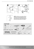
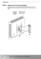
STEP 6 - Option 1: Installing on a wood stud wall Note: Drywall covering the wall must not exceed 5/8" (16 mm). 1 Locate the stud. Verify the center of the stud with an edge-to-edge stud finder. 2 Align the center of the wall plate template (11) at the height you determined in the previous step and make sure that it is level. Tape the wall plate template to the wall, then use a pencil to mark the lag bolt hole locations (2) on the stud centers. Remove the wall plate template. 3 Drill pilot holes to a depth of 2 3/4 in. (69 mm) using a 7/32 in. (5.5 mm) diameter drill bit. Note: Minimum wood stud size: Common 2 x 4 in. (51 x 102 mm). Nominal 1.5 x 3.5 in. (38 x 89 mm) 2 3/4 in. (69 mm) 7/32 in. Y UP (5.5 mm) 4 Align the wall plate (12) with the pilot holes, insert the lag bolts (13) through the holes in the wall plate assembly, then tighten the lag bolts only until they are firm against the wall plate assembly. CAUTION: Avoid potential injuries or property damage! DO NOT over-tighten the lag bolts (13). 12 Need help? Call 1-800-620-2790 (U.S. and Canada)
-
 1
1 -
2
-
3
-
4
-
5
-
6
-
 7
7 -
 8
8 -
 9
9 -
 10
10 -
 11
11 -
 12
12 -
 13
13 -
 14
14 -
 15
15 -
 16
16 -
 17
17 -
18
-
19
 |
 |
