Ryobi AG452K English Manual - Page 10
Operation - angle grinder brushes
 |
View all Ryobi AG452K manuals
Add to My Manuals
Save this manual to your list of manuals |
Page 10 highlights
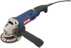
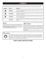
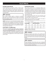
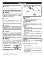
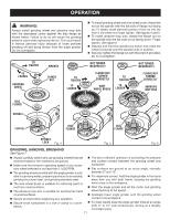
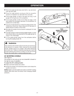
OPERATION WARNING: Do not allow familiarity with tools to make you careless. Remember that a careless fraction of a second is sufficient to inflict serious injury. WARNING: LOCK-ON BUTTON Always wear safety goggles or safety glasses with side shields when operating power tools. Failure to do so could result in objects being thrown into your eyes resulting in possible serious injury. SWITCH TRIGGER Fig. 3 WARNING: Do not use any attachments or accessories not recommended by the manufacturer of this tool. The use of attachments or accessories not recommended can result in serious personal injury. DANGER: Never attach a wood cutting or carving blade of any type to this angle grinder. It is only designed for grinding and sanding. Use for any other purpose is not recommended and creates a hazard, which will result in serious injury. DANGER: Never use your grinder with the guard removed. It has been designed for use only with the guard installed. Attempting to use grinder with guard removed will result in loose particles being thrown against the operator resulting in serious personal injury. SWITCH TRIGGER See Figure 3. To turn the angle grinder ON, depress the switch trigger. To turn it OFF, release the switch trigger. LOCK-ON BUTTON See Figure 3. The angle grinder is equipped with a lock-on feature, which is convenient for continuous grinding/sanding for extended periods of time. To lock-on: Depress the switch trigger. Push in and hold the lock-on button, located on the side of the handle. Release the switch trigger. Release the lock-on button and the angle grinder will continue running. To release the lock, depress and release the switch trigger. If the lock-on feature is engaged during use and the angle grinder becomes disconnected from the power supply, disengage the lock-on feature immediately. DANGER: Use ONLY Type 27 depressed center wheels (such as the one provided with this product). Never attach a Type 1 straight or cut-off wheel to this angle grinder. This product is only designed for grinding and sanding. Use for any other purpose is not recommended and creates a hazard, which will result in serious injury. Type 27 − OK to use Type 1 − do not use APPLICATIONS You may use this tool for the purposes listed below: Grinding metals Sanding wood or metal surfaces Wire brushing rusted or painted surfaces CAUTION: Never cover air vents. They must always be open for proper motor cooling. INSTALLING accessory wheels See Figures 4 - 6. Unplug the angle grinder. Depress and hold spindle lock button and rotate flange nut with provided wrench until spindle locks. NOTE: To prevent damage to the spindle or spindle lock, always allow motor to come to a complete stop before engaging spindle lock. Loosen and remove flange nut from spindle. Do not remove disc flange. Make sure flats on the bottom of disc flange are engaged with flats on spindle. Place the accessory wheel over the spindle. 10
-
 1
1 -
2
-
3
-
4
-
 5
5 -
 6
6 -
 7
7 -
 8
8 -
 9
9 -
 10
10 -
 11
11 -
 12
12 -
 13
13 -
 14
14 -
 15
15 -
16
 |
 |