Ryobi CSB142LZK English Manual - Page 18
Length Of Cut Scale, Cross Cutting/rip Cutting, Bevel Cutting
 |
View all Ryobi CSB142LZK manuals
Add to My Manuals
Save this manual to your list of manuals |
Page 18 highlights
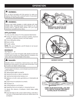
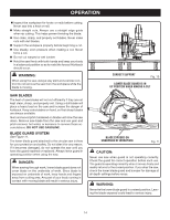
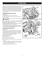
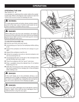
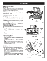
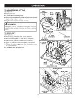
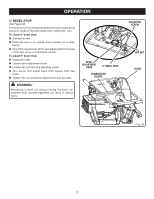
OPERATION LENGTH OF CUT SCALE See Figure 19. The saw is equipped with a length of cut scale on its base. It is parallel with the saw blade and can be used to measure the distance into the material the blade cuts. NOTE: Six inches is the maximum length of cut that you can measure. Also, it is accurate only when the depth of cut is set at full maximum depth. CROSS CUTTING/RIP CUTTING See Figures 20 - 21. When making a cross cut or rip cut, align the line of cut with the outer blade guide notch on the base as shown in the figure. Since blade thicknesses vary, always make a trial cut in scrap material along a guideline to determine how much, if any, you must offset the guideline to produce an accurate cut. NOTE: The distance from the line of cut to the guideline is the amount you should offset the guide. to rip cut without edge guide: Use a guide when making long or wide rip cuts with the saw. Secure the workpiece. Clamp a straight edge to the workpiece using C-clamps. Saw along the straight edge to achieve a straight rip cut. NOTE: Do not bind the blade in the cut. To rip cut with edge guide: Secure the workpiece. Position the face of the edge guide firmly against the edge of workpiece. Guide the saw along the edge to achieve a straight rip cut. NOTE: The guiding edge of the workpiece must be straight for the cut to be straight. Use caution to prevent the blade from binding in the cut. BEVEL CUTTING See Figures 22 - 23. To make the best possible cut, follow these helpful hints. Align the line of cut with the inner blade guide notch on the base when making 45° bevel cuts. Make a trial cut in scrap material along a guideline to determine how much you should offset the guideline on the cutting material. Adjust the angle of the cut to any desired setting between zero and 51.5°. Refer to TO ADJUST BEVEL SETTING next. 18 0 1 2 0 3 1 2 3 LENGTH OF CUT SCALE Top View of Saw Fig. 19 Guideline Blade Guide Notch C-CLAMP Fig. 20 STRAIGHT EDGE 45 30 51.5 15 GUIDELINE WORKPIECE C-CLAMP Fig. 21
-
 1
1 -
2
-
3
-
4
-
5
-
6
-
7
-
8
-
9
-
10
-
11
-
12
-
 13
13 -
 14
14 -
 15
15 -
 16
16 -
 17
17 -
 18
18 -
 19
19 -
 20
20 -
 21
21 -
 22
22 -
 23
23 -
24
 |
 |
