Ryobi HP53LK Operation Manual - Page 7
Operation - torque
 |
View all Ryobi HP53LK manuals
Add to My Manuals
Save this manual to your list of manuals |
Page 7 highlights
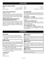
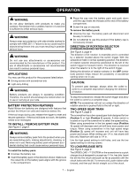
OPERATION WARNING: Do not allow familiarity with products to make you careless. Remember that a careless fraction of a second is sufficient to inflict serious injury. WARNING: Always wear eye protection with side shields marked to comply with ANSI Z87.1. Failure to do so could result in objects being thrown into your eyes resulting in possible serious injury. WARNING: Do not use any attachments or accessories not recommended by the manufacturer of this product. The use of attachments or accessories not recommended can result in serious personal injury. APPLICATIONS You may use this product for the purposes listed below: Driving screws with screwdriver bits Light-duty drilling WARNING: Battery products are always in operating condition. Therefore, the switch should always be locked when not in use or carrying at your side. BATTERY PROTECTION FEATURES Ryobi lithium-ion batteries are designed with features that protect the lithium-ion cells and maximize battery life. If the tool stops during use, release the trigger to reset and resume operation. If the tool still does not work, the battery needs to be recharged. TO INSTALL / remove BATTERY PACK See Figure 2, page 9. WARNING: Always remove battery pack from the product when you are assembling parts, making adjustments, cleaning, or when not in use. Removing battery pack will prevent accidental starting that could cause serious personal injury. To install the battery pack: Unscrew the battery cap. Insert the battery pack in the direction shown. Make sure the raised rib on the battery pack aligns with the groove in the compartment. Place the cap over the battery pack and push down until the cap meets the threads at the end of the battery compartment. Screw the cap on securely. To remove the battery pack: Unscrew the cap. The battery pack will disconnect and be easy to remove. Do not attempt to use this product if the battery cap is not securely closed. DIRECTION OF ROTATION SELECTOR (FORWARD/REVERSE/center lock) See Figure 3, page 9. The direction of bit rotation is reversible and is controlled by a selector located above the switch trigger. With the screwdriver held in normal operating position, the direction of rotation selector should be positioned to the left of the switch trigger for forward motion. The direction is reversed when the selector is to the right of the switch trigger. Setting the direction of rotation selector in the OFF (center lock) position helps reduce the possibility of accidental starting when not in use. CAUTION: To prevent gear damage, always allow the collet to come to a complete stop before changing the direction of rotation. To stop the screwdriver, release the switch trigger and allow the collet to come to a complete stop. NOTE: The screwdriver will not run unless the direction of rotation selector is pushed fully to the left or right. TWO-SPEED GEAR TRAIN See Figure 4, page 9. The screwdriver has a two-speed gear train designed for low (Position 1) or high (Position 2) speeds. A slide switch is located on top of the screwdriver to select the speed setting. When using screwdriver in the low speed range (Position 1), speed will decrease and unit will have more power and torque. When using screwdriver in the high speed range (Position 2), speed will increase and unit will have less power and torque. When drilling use 1/4 in. hex shank drill bits only. Maximum drill size is 1/4 in. Use the high speed setting to drill holes, and use the low speed setting for driving screws. TO LOAD/RELEASE BITS See Figure 5, page 9. The SPEEDLOAD +™ SYSTEM on the screwdriver is a quick change chuck designed to accept any 1/4 in. hex bits. Insert the bit into the chuck and push as far as possible until the chuck locks onto the bit. To remove a bit, push rubber collar forward, and then pull the bit straight out of the chuck. 7 - English
-
 1
1 -
 2
2 -
 3
3 -
 4
4 -
 5
5 -
 6
6 -
 7
7 -
 8
8 -
 9
9 -
 10
10 -
 11
11 -
 12
12 -
13
-
14
-
15
-
16
-
17
-
18
-
19
-
20
-
21
-
22
-
23
-
24
 |
 |