Ryobi HPL52K User Manual - Page 14
Attaching The Featherboard, Inserting The Starting Pin, Installing The Miter Gauge, Attaching
 |
View all Ryobi HPL52K manuals
Add to My Manuals
Save this manual to your list of manuals |
Page 14 highlights
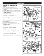
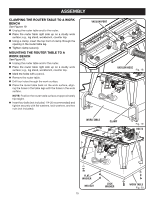
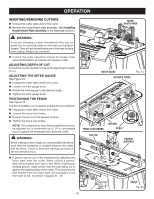
ASSEMBLY ATTACHING THE FEATHERBOARD See Figure 15. n Unplug the router table and/or the router. Insert the featherboard bolts through the slots in the fence 3 2 assembly. 1 0 1 Inch Slide the featherboard over the featherboard bolts. Install the fence lock knobs and carriage bolt washers over the carriage bolts. Tighten the fence lock knobs. INSERTING THE STARTING PIN See Figure 16. Place the starting pin on the router table and use it as a pivot point when cutting small, odd-shaped pieces. NOTE: It is not necessary to use the fence when you are using the starting pin, but the bit guard should be used to cover the cutter. Additionally, only use piloted cutters when using the starting pin. n Unplug the router table and/or the router. 3 n Place the starting pin into the hole to the right1of th2 e router table throat opening. 0 1 n Push the pin in to secure. Inch INSTALLING THE MITER GAUGE See Figure 17. n Unplug the router table and/or the router. With the router table right side up, and the front edge closest to you, place the miter gauge bar in the slot near the front of the table with the pointer on the right. ATTACHING THE VACUUM HOSE See Figure 18. The vacuum port molded into the fence will accept either a 1-1/4 in. or 2-1/2 in. vacuum attachment. FENCE LOCK KNOB MITER GAUGE BAR 3 2 1 0 1 Inch SLOT FEATHERBOARD BOLT 3 2 1 0 1 Inch FEATHERBOARD CARRIAGE BOLT WASHER Fig. 15 STARTING PIN DIFREEECDTION STARTING PIN HOLES Fig. 16 1 Inch MITER GAUGE POINTER 3 2 1 0 1 Inch SLOT 14 Fig. 17
-
 1
1 -
2
-
3
-
4
-
5
-
6
-
7
-
8
-
 9
9 -
 10
10 -
 11
11 -
 12
12 -
 13
13 -
 14
14 -
 15
15 -
 16
16 -
 17
17 -
 18
18 -
 19
19 -
20
-
21
-
22
-
23
-
24
-
25
-
26
-
27
-
28
-
29
-
30
-
31
-
32
-
33
-
34
-
35
-
36
-
37
-
38
-
39
-
40
-
41
-
42
-
43
-
44
-
45
-
46
-
47
-
48
-
49
-
50
-
51
-
52
-
53
-
54
-
55
-
56
 |
 |
