Ryobi HPL52K User Manual - Page 18
Warning, Adjusting Depth Of Cut, Adjusting The Miter Gauge, Positioning The Fence
 |
View all Ryobi HPL52K manuals
Add to My Manuals
Save this manual to your list of manuals |
Page 18 highlights
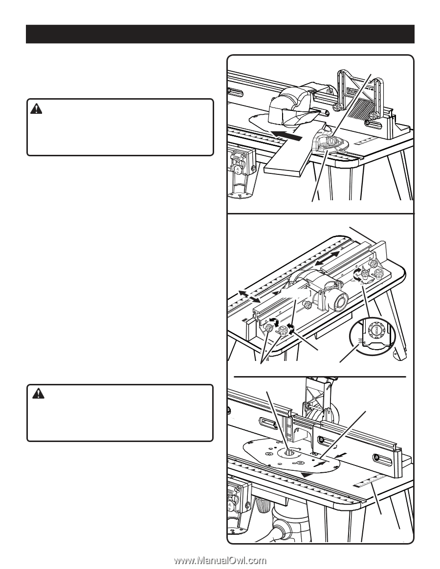
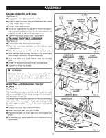
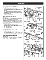
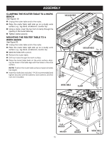
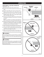
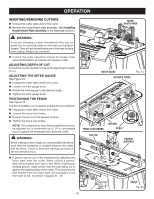
OPERATION INSERTING/REMOVING CUTTERS n Unplug the router table and/or the router. n Remove the router/insert plate assembly. (See Installing Router/Insert Plate Assembly in the Assembly section.) WARNING: 3 2 1 0 1 Inch If you are changing a cutter immediately after use, be careful not to touch the cutter or collet with your hands or fingers. They will get burned because of the heat buildup from cutting. Always use a wrench. MITER GAUGE KNOB 3 2 1 0 1 Inch n Consult the router operator's manual for proper cutter removal/installation procedure and replace cutter. ADJUSTING DEPTH OF CUT Consult the router operator's manual for adjusting the depth of cut. ADJUSTING THE MITER GAUGE See Figure 24. n Unplug the router table and/or the router. n Loosen the miter gauge knob. n Rotate the miter gauge to the desired angle. n Tighten the miter gauge knob. POSITIONING THE FENCE See Figure 25. The fence enables you to support and guide the workpiece. n Unplug the router table and/or the router. n Loosen the fence lock knobs. n Position the fence to the desired location. n Tighten the fence lock knobs. NOTE: The outfeed fence has joining capabilities and can be adjusted out in increments up to 1/4 in. and enable you to support the workpiece as it exits the cutter. WARNING: When making a side or edge cut, never position the fence such that the workpiece is located between the cutter 3 2 and the fence. Failure to heed this warning can result i0n 1 1 serious personal injury. Inch MITER GAUGE OUTFEED FENCE Fig. 24 1 Inch FEDEIDRECTION LOOSEN 0 1/4 FENCE LOCK KNOBS TIGHTEN SCALE CUTTER PROPER DISTANCE n A groove can be cut in the workpiece by adjusting the fence back from the cutter. When cutting a groove, feed the workpiece from right to left. When widening an existing groove, make certain that the side being cut is against the leading edge of the cutter. This would be the side farthest from the fence when the workpiece is fed from right to left. As shown in figures 21 - 23. DIFREEECDTION 3 2 3 1 2 0 1 Inch SCALE Fig. 25 18
-
 1
1 -
2
-
3
-
4
-
5
-
6
-
7
-
8
-
9
-
10
-
11
-
12
-
 13
13 -
 14
14 -
 15
15 -
 16
16 -
 17
17 -
 18
18 -
 19
19 -
 20
20 -
 21
21 -
 22
22 -
 23
23 -
24
-
25
-
26
-
27
-
28
-
29
-
30
-
31
-
32
-
33
-
34
-
35
-
36
-
37
-
38
-
39
-
40
-
41
-
42
-
43
-
44
-
45
-
46
-
47
-
48
-
49
-
50
-
51
-
52
-
53
-
54
-
55
-
56
 |
 |