Ryobi P2606A Operation Manual - Page 3
Fig. 4, Fig. 7, Fig. 5, Fig. 8, Fig. 9, Fig. 10, Fig. 6
 |
View all Ryobi P2606A manuals
Add to My Manuals
Save this manual to your list of manuals |
Page 3 highlights
Fig. 4 A Fig. 7 B A - Lock-out button (bouton de verrouillage, botón del seguro) B - Switch trigger (gâchette, gatillo del interruptor) Fig. 5 B Fig. 8 Fig. 10 A A A - Rotating handle button (bouton de la poignée pivotante, perilla del mango giratorio) B - Rear Handle (poignée arrière, mango trasero) Fig. 6 PROPER OPERATING POSITION BONNE POSITION DE TRAVAIL POSICIÓN CORRECTA PARA EL MANEJO DE LA HERRAMIENTA Fig. 9 A B A - Scabbard (fourreau, funda) A - Guard teeth (dents de coupe, dientes de proteción) B - Cutting teeth (dents de coupe, dientes de corte) iii
-
 1
1 -
 2
2 -
 3
3 -
 4
4 -
 5
5 -
 6
6 -
 7
7 -
 8
8 -
 9
9 -
10
-
11
-
12
-
13
-
14
-
15
-
16
-
17
-
18
-
19
-
20
-
21
-
22
-
23
-
24
-
25
-
26
-
27
-
28
-
29
-
30
-
31
-
32
-
33
-
34
-
35
-
36
-
37
-
38
 |
 |

iii
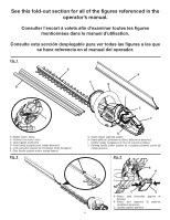
Fig. 4
A - Lock-out button (bouton de verrouillage,
botón del seguro)
B - Switch
trigger
(gâchette,
gatillo
del
interruptor)
Fig. 7
Fig. 5
Fig. 8
Fig. 9
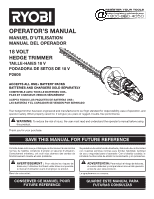
A - Guard teeth (dents de coupe, dientes de
proteción)
B - Cutting teeth (dents de coupe, dientes de
corte)
Fig. 10
A - Scabbard (fourreau, funda)
A
B
A
B
A
Fig. 6
PROPER OPERATING POSITION
BONNE POSITION DE TRAVAIL
POSICIÓN CORRECTA PARA EL MANEJO
DE LA HERRAMIENTA
A
B
A - Rotating handle button (bouton de la poignée
pivotante, perilla del mango giratorio)
B - Rear Handle (poignée arrière, mango
trasero)