Ryobi P300 English Manual - Page 10
Loading The Tool With Brads - stapler
 |
View all Ryobi P300 manuals
Add to My Manuals
Save this manual to your list of manuals |
Page 10 highlights
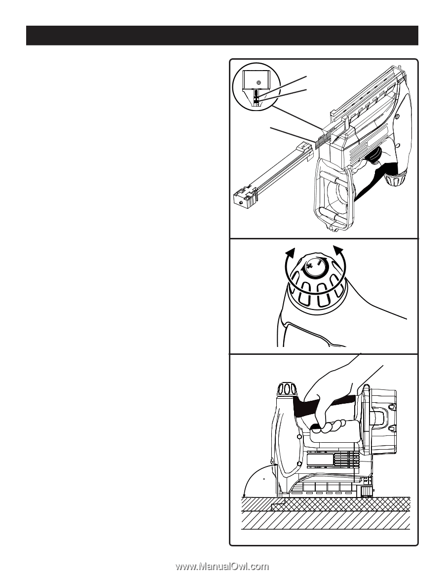
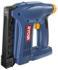
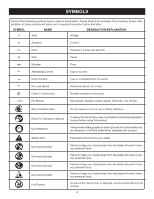
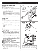
OPERATION LOADING THE TOOL WITH BradS See Figure 5. Remove battery pack from the tool. Hold tool upside down; squeeze latch and slide base open. Place brads in the center of the channel with "T" head sitting on the slot base. Close base while making sure brad strip stays upright in channel. NOTE: There are two channels for the brads. Use the smaller channel for brads sized 3/4 in. to 1 in. Use the larger channel for brads sized 1-1/4 in. Refer to molding on the tool. Make sure that the latch is securely locked in place. Reattach battery pack to tool. SETting DEPTH See Figure 6. Rotate the depth adjustment knob clockwise to use more force for nailing or stapling. Rotate depth adjustment knob counter clockwise to use less force for nailing or stapling. Test on a scrap piece of the same material you are using to achieve the desired results. NOTE: Harder materials will require more force to nail or staple. NAILing OR STAPLing See Figure 7. Hold handle firmly with magazine flat to workpiece forming a 90º angle. Press the activation foot of the nailer/stapler down against the workpiece to disengage the safety interlock. The activation foot must be depressed before the switch trigger is depressed. Release the switch trigger and activation foot before driving another brad or staple. NOTE: You must release the activation foot and switch trigger after each brad or staple to reset the tool. The tool will not fire another staple or brad until the activation foot and switch trigger are released. removing a jammed brad/staple Remove battery pack from the tool. Hold tool upside down; squeeze latch and slide base open. Remove unused brads/staples from magazine. Remove jammed brad/staple with needle nose pliers. NOTE: You must remove jammed brad/staple before using tool any further. If you try to fire a brad/staple while the tool is jammed, you could cause damage to the mechanism. 10 BradS increase force 90 3/4 in. to 1 in. 1-1/4 in. Fig. 5 decrease force Fig. 6 Fig. 7
-
 1
1 -
2
-
3
-
4
-
 5
5 -
 6
6 -
 7
7 -
 8
8 -
 9
9 -
 10
10 -
 11
11 -
 12
12
 |
 |